
Starlink officially launched their Mobile (also called Roam) service tier way back in May of 2022, but the lack of official accessories made for RV’s continues to baffle me and many of my readers. The most requested accessory for Starlink Roam is a 12V DC power supply. So far, Starlink hasn’t delivered in that area. Thankfully, 3rd party companies have answered the call, and there are several ways to create your own Starlink DC power supply.
With a few supplies, and basic electrical skills, you can build your own DC power supply for Starlink. It can be powered by your existing 12V, 24V, or 48V power system. If you don’t want to deal with inverters, and wish to run Starlink directly from your battery system, this is the guide for you.
In this tutorial, I will show you two popular methods to build a 12V DC power supply for the Standard (rectangular) Starlink dish. I will first explain why you would even want one. Then I will talk about all the supplies needed for this project. Finally, I’ll walk you through the process step by step.
Warning: Use this guide at your own risk. Electricity can be dangerous if proper safety precautions aren't followed. Modifying any of the Starlink hardware will void your warranty.
Table of Contents
Why DC Power?
RV’s, vans, overlanding rigs, and even off-grid cabins use batteries for electricity. Efficiency is extremely important to maximize the amount of energy available. The Starlink router doubles as a power supply for the dish. It converts AC power from the wall plug into usable 48V DC power for the dish.
That’s fine for residential applications, where you are connected to the grid and have AC power readily available. But with an off-grid battery system, you need an inverter to get AC power. So you would be going from DC to AC, and then back to DC in the router. That extra conversion to AC creates an efficiency issue, and wastes precious energy.
Two Methods To Build A DC Power Supply
This guide is on its second version. When I first wrote it, Yaosheng wasn’t making their Starlink cable adapter or POE injector. If you wanted to build a DC power supply for Starlink, you had to be comfortable cutting the cable in order to install an RJ45 connector.
Now, building a 12V power supply for Starlink Roam is a lot easier. Using a special adapter, you can avoid cutting the Starlink cable. No more worrying about wiring pinouts or damaging your hardware. It’s virtually plug and play these days.
So, just pick one method below to see how I built my own DC power supply:
Method 1 – The Easy Way – This method doesn’t require any modifications to the Starlink equipment. No cable cutting, no RJ45 connectors. This method is more expensive, and recommended for people without electrical skills.
Method 2 – The Cheap Way – This is the older method, which involves modifying the Starlink cable with an RJ45 connector. This way is much cheaper, but involves more electrical work.
Method 1 – The Easy Way
If you want a plug and play DC power supply for Starlink, the easy way that follows is for you. With just a few components, you can run the Standard Starlink dish from your RV/van/off-grid battery system.
Supplies Needed
Note: This article may contain affiliate links for the products mentioned

48V DC-DC Converter – #CommissionsEarned

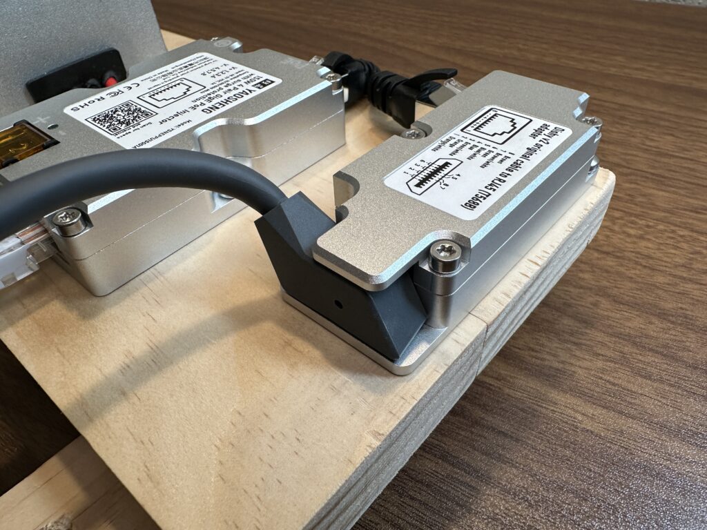
Yaosheng Dishy Cable Adapter – #CommissionsEarned

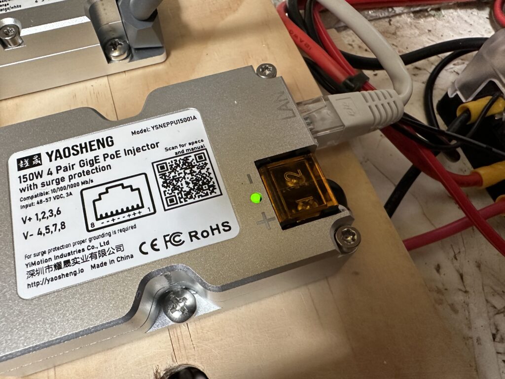
Yaosheng POE Injector – #CommissionsEarned
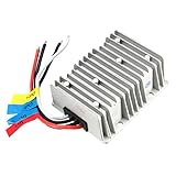
- 48V DC to DC converter – This DC/DC power supply takes either 12V or 24V from your battery and converts it to the 48V required to power the Starlink dish. If your battery system is already 48V, you can skip this.
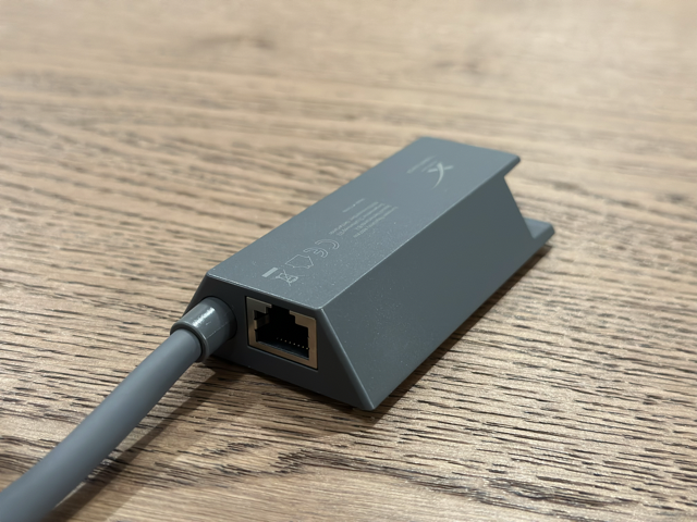
- Yaosheng Dishy Cable Adapter – This adapter accepts the Starlink cable on one end, and has an RJ45 connector on the other end. This is the key component that lets us avoid cutting the Starlink cable.
- Yaosheng Passive POE injector – A POE (power over Ethernet) injector takes the 48V from the DC power supply and sends it to the Starlink dish. It has 2 Ethernet ports, one for the dish, and one for the Wifi router.
- Wifi router – You can’t use the Starlink router with this method, so you’ll need an aftermarket router. Almost any of them will do, but make sure it uses 12V like the one I linked, so it can be hooked up to your battery.
- Screwdriver – You will need a small screwdriver to connect the power supply leads to the POE injector.
- Crimp/splice connectors – For connecting your power supply wiring to your battery system.
- Crimp tool – To crimp the electrical connectors, some pliers would also work.
- Ethernet cable – You will need a Ethernet patch cable to go from your router to the POE injector. Usually the aftermarket router will come with one.
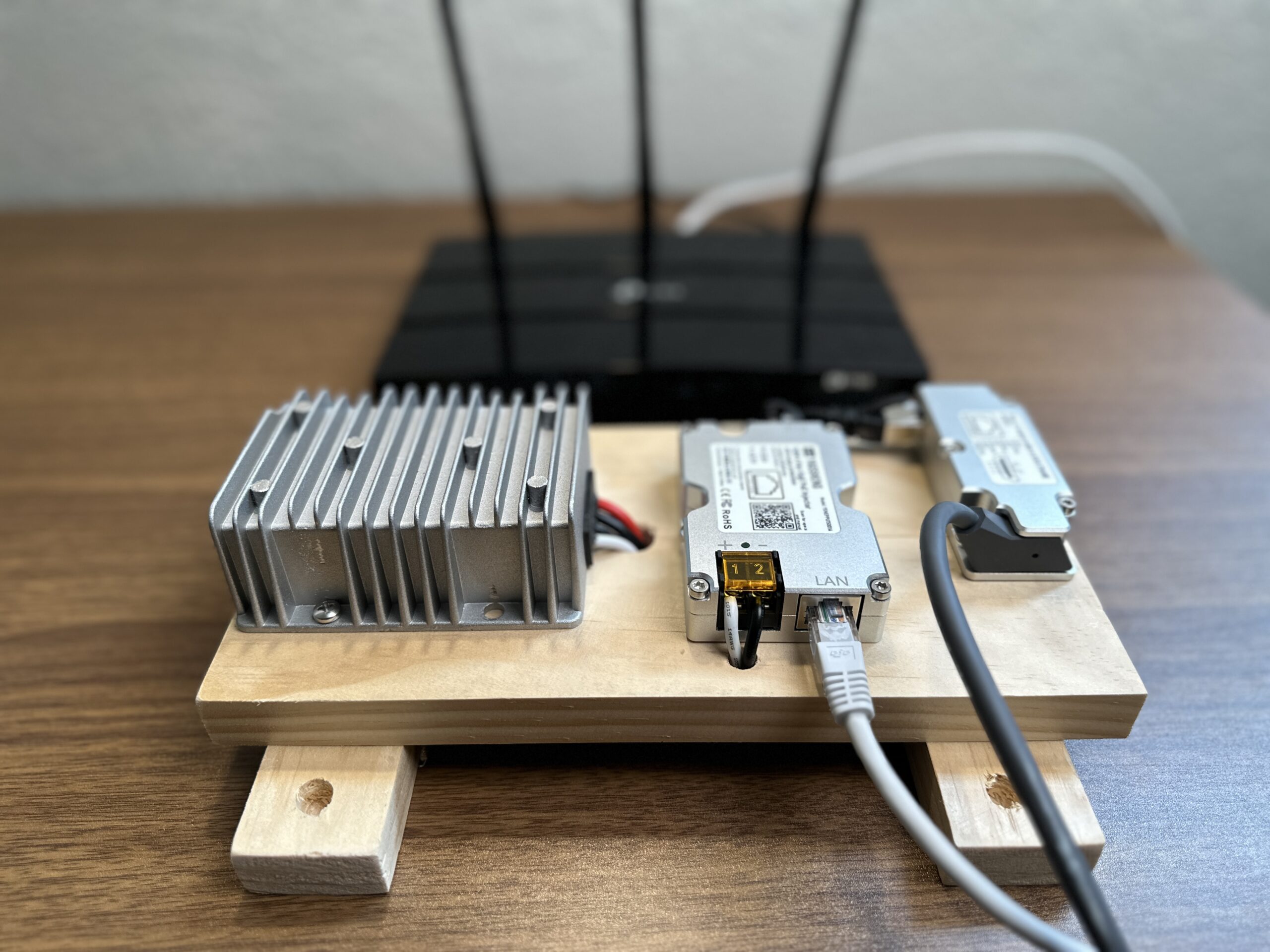
Step 1 – Mount The Components
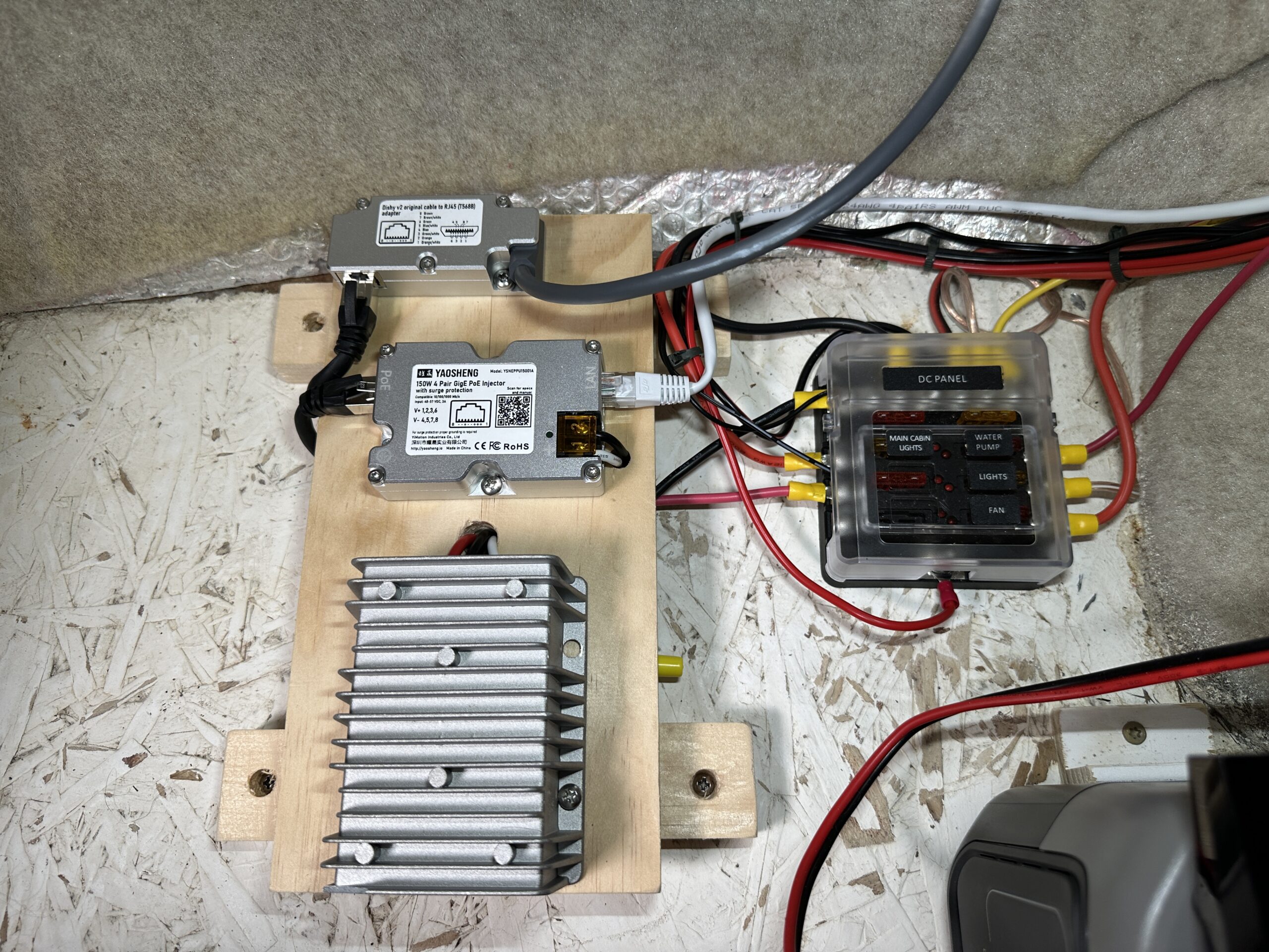
In order to mount all the various components in my RV, I just screwed everything to a scrap piece of wood that I had laying around. You can be as creative as you wish here. Personally, I just needed something clean and functional.
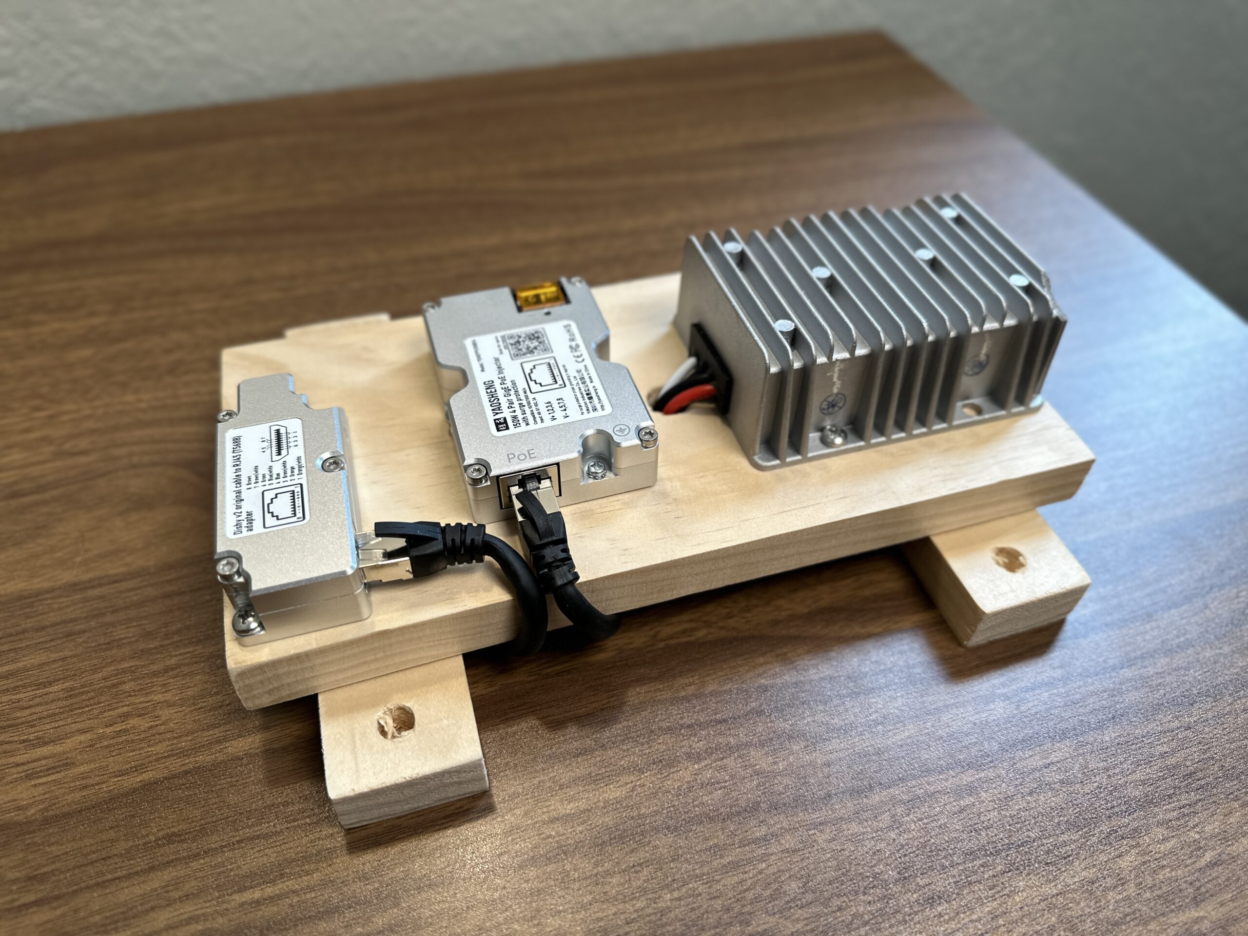
There are a few considerations to think about when laying out your components. The Yaosheng adapter and POE injector are connected with the included Ethernet cable. You’ll want to align the components so that the connectors are easily accessible. As you can see in the photo above, I oriented the adapter and POE injector so that the POE ports faced each other.
Also, keep in mind that the output leads from the power supply need to be routed into the POE injector. I avoided having to splice in additional wire by installing the POE injector close to the power supply.
Finally, think about how your enclosure will mount in your RV/van/cabin/etc. The Starlink cable comes out of one end of the cable adapter. You also have the router Ethernet cable coming out of the POE injector. Lastly, you will have the power supply input leads going to your battery system. Figure out the best way to lay out the components so that you can easily route all the cables, and access the connectors in the future if needed.
Step 2 – Connect The Components
After you’ve assembled all the components, it’s time to hook everything up. Without any DC power applied to the power supply, make the following connections:
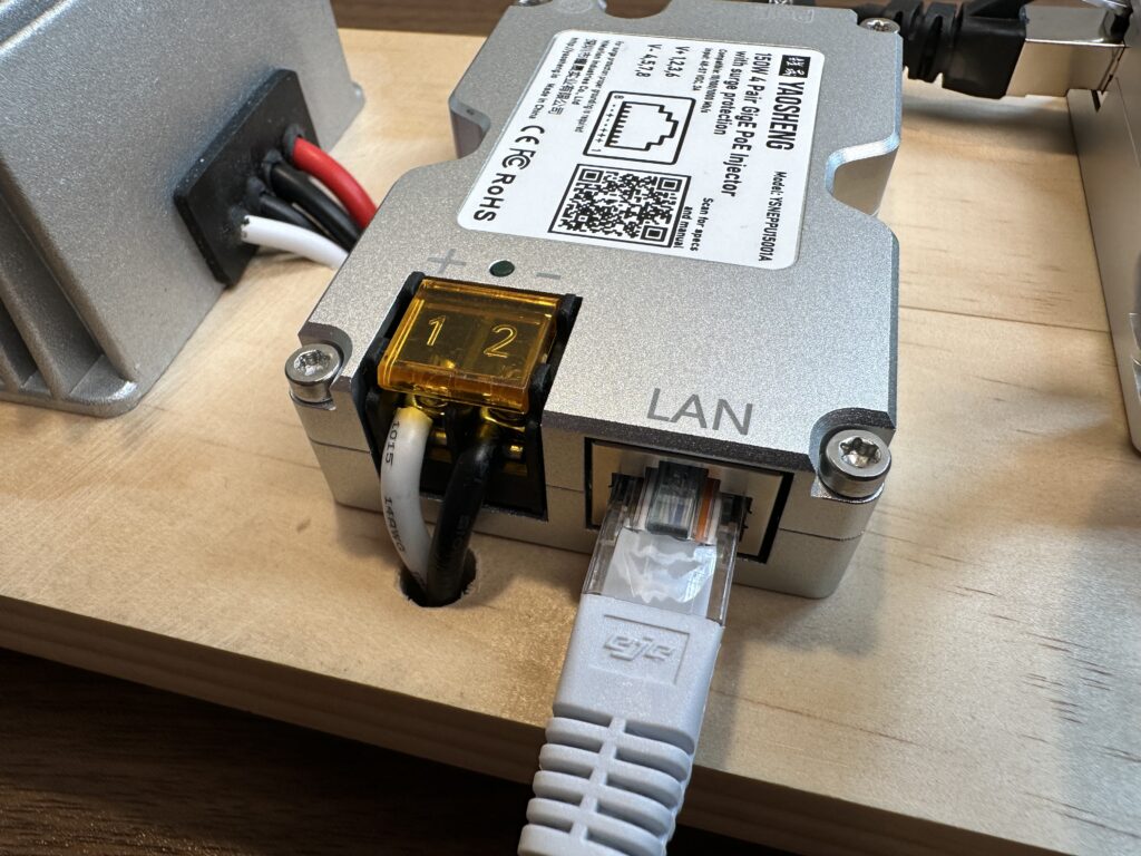
- Power supply 12V output to POE injector input – Connect the white (+) wire from the power supply to the positive (+) terminal of the POE injector. Connect the black (-) wire from the power supply to the negative (-) terminal of the POE injector.
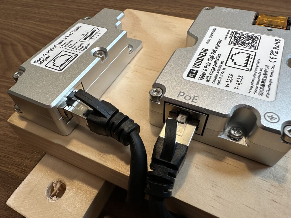
- Cable adapter to POE injector – Use the shielded Ethernet cable included with the Yaosheng cable adapter to connect the adapter to the “POE” port on the POE injector.
- Starlink to cable adapter – Connect the Starlink cable to the Yaosheng cable adapter.
- Router to POE injector – Connect the router Internet/WAN port to the POE injector “Data” port using an Ethernet cable.
Step 3 – Create The Router Power Supply Cable
Before you modify the router power supply cable, it’s a good idea to go through the router setup and configuration. It’s just easier to do this now rather than worrying about it later. The specifics will depend on your router model, but follow the manufacturer instructions for how to perform the initial setup. You should set up a Wifi name and password on your router before continuing, so that when it comes time to test your power supply, you can connect and test it right away.
Most household routers plug into the wall socket with a power adapter. The output of the power adapter is usually 12V DC. If you purchased the TP-Link router I linked above, all you need to do is cut off the AC-DC converter, and wire the 12V DC plug to your RV/van/etc. battery system.
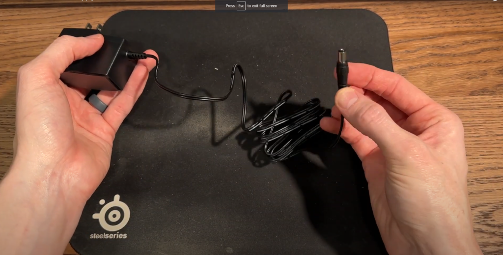


For the TP-Link router power supply, the black lead with the white strips is positive (+) and the plain black lead is negative (-). If you are using a different router, double check the specifications to be sure it can be wired up to a 12V source. Be sure to also check the polarity of the power plug leads.
Step 4 – Plug Everything In
Now it’s time to make the final power connections and install the power supply in your RV/van/cabin/etc. Supply 12V/24V DC to the input leads of the DC to DC power supply. Connect the positive (+) battery lead to the red (+) input wire from the power supply. Connect the negative (-) battery lead to the black (-) input wire from the power supply. It’s best practice to place a fuse on the positive (+) lead going into the power supply.
Supply 12V DC to the router power supply (if using the TP-Link router mentioned in the supplies list). Again, it’s best practice to install a fuse on the positive (+) power leads. Typically, you are going to tap into your RV/van fuse block for 12V power, which satisfies the fuse requirement. But if you are doing something else, be sure to follow best practices.
At this point, the power supply is ready to test. If you decided to build the power supply “the easy way”, go ahead and skip down to the testing section.
Method 2 – The Cheap Way
When I first wrote this article, the Yaosheng adapter didn’t exist. The only way to build a DC power supply was to cut the Starlink cable in order to install an RJ45 connector. The RJ45 connector was necessary to be able to plug into the POE injector.
The cheap method involves more work, but the tradeoff is huge cost savings. The Yaosheng POE injector and cable adapter combo is about 7 times more expensive than the POE injector used for the cheap method. If you’re comfortable cutting the Starlink cable and installing RJ45 connectors, you can save a lot of money by building this version of Starlink DC power supply.
Cheap Method Video Tutorial
Note: Some ad blockers will block our video player. If you don’t see the video, try disabling your ad blocker, and then reload the page.
The video is also available on our YouTube channel if you prefer to watch there.
Supplies Needed
48V DC-DC Converter – #CommissionsEarned

POE Injector – #CommissionsEarned

Shielded RJ45 Connectors – #CommissionsEarned
Before you can get started, you need several supplies to create the DC power supply:
- Starlink Ethernet Adapter – In this tutorial I am modifying a Starlink Ethernet Adapter instead of modifying the Starlink cable directly. I prefer this method because I can easily move my dish back to my home and plug it right into the Starlink router. If you prefer, you can skip the Ethernet Adapter and just modify the Starlink cable instead.
- 48V DC to DC converter – This DC/DC power supply takes either 12V or 24V from your battery and converts it to the 48V required to power the Starlink dish. If your battery system is already 48V, you can skip this.
- POE injector – A POE (power over Ethernet) injector takes the 48V from the DC power supply and sends it to the Starlink dish. It has 2 Ethernet ports, one for the dish, and one for the Wifi router.
- Wifi router – You can’t use the Starlink router with this method, so you’ll need an aftermarket router. Almost any of them will do, but make sure it uses 12V like the one I linked, so it can be hooked up to your battery.
- Wire cutters/strippers – You need something to cut the Starlink cable and to strip back the wire on the PoE injector/power supply
- Screwdriver – A small flat head, eyeglasses screwdriver would work fine
- Crimp/splice connectors – For the battery, DC/DC converter, and POE injector wiring
- Crimp tool – To crimp the electrical connectors, some pliers would work
- RJ45 crimp tool – We will be installing our own RJ45 connectors, so you will need a tool that can crimp them on the cable.
- RJ45 shielded connectors – We’ll be replacing the proprietary Starlink connector with a shielded RJ45
- Ethernet cable – You will need a Ethernet patch cable to go from your router to the POE injector. Usually the aftermarket router will come with one. We will be modifying one end of the Ethernet cable.
Step 1 – Modify The Starlink Ethernet Adapter
The first thing we need to do is replace the proprietary Starlink connector on the Ethernet Adapter with a shielded RJ45 connector. This will allow the dish to be powered by our own power supply, instead of the Starlink router. If you have opted to skip the Ethernet Adapter and modify the Starlink cable directly, the steps are the same. I’m modifying the Ethernet Adapter so I don’t have to cut into my Starlink cable, but it works fine either way.
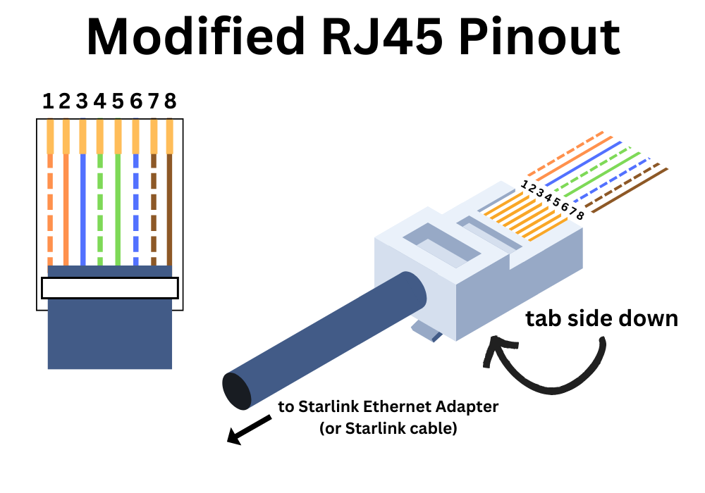
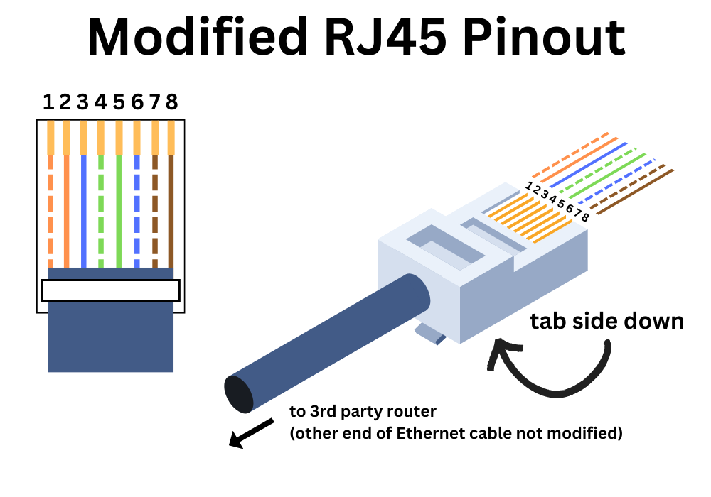
Converting To Starlink POE
There is one caveat, though. The POE (power over Ethernet) pinout used by Starlink is different than the standard POE pinout. To solve this problem, we just need to wire our RJ45 connectors a bit differently from the T-568B standard normally used when terminating RJ45 connectors. Here is the pinout that you need to use for the shielded RJ45 connector on the Starlink Ethernet Adapter (or Starlink cable):
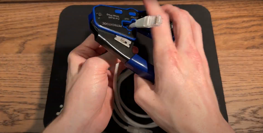
Prepare The Cable
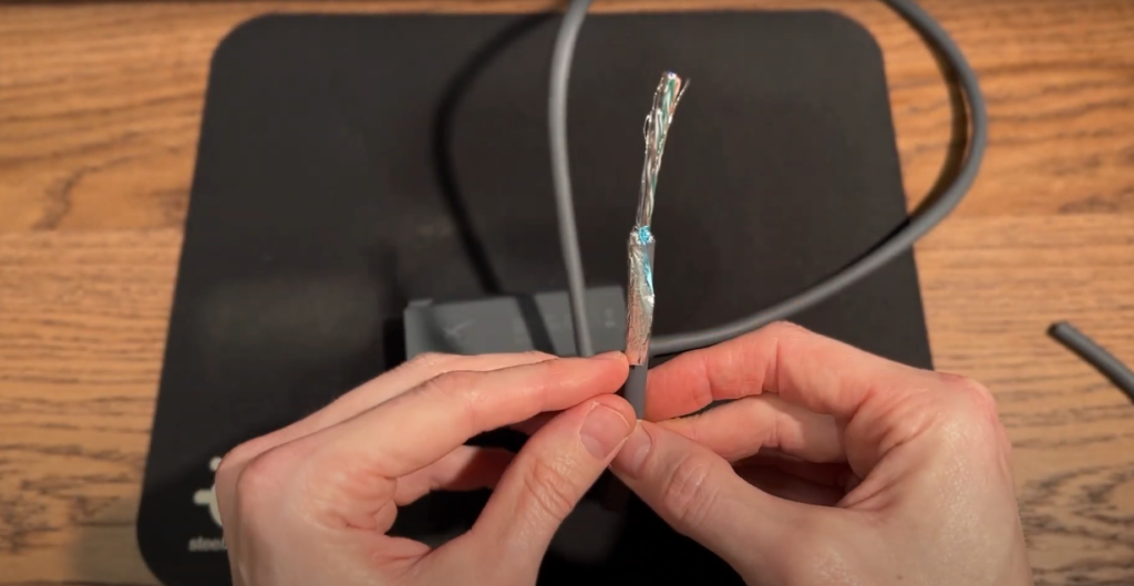

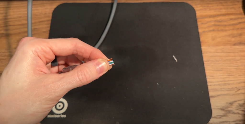
Use wire cutters to cut the Starlink router connector off the Ethernet Adapter (or Starlink cable). Then, strip off about an 2 inches of insulation to expose the conductors and shielding. Most crimp tools have a wire stripper blade just for this job. Peel back the shielding foil and fold it back down the cable, we will deal with that later. Also find the drain wire. It’s the bare conductor. Fold that back out of the way for now. You should now be left with 8 twisted pairs, 16 wires total. 4 of the pairs are larger gauge wire, the other 4 are smaller in size. Trim back the smaller pairs, we won’t be needing them.
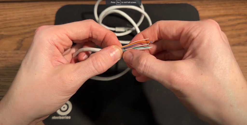
Untwist all 4 pairs and do your best to straighten out each of the 8 wires. Once they are straightened out, hold the cable in your left hand, with the wires pointing across your body to the right. Arrange the wires according to the pinout above. When they are in the correct order, do your best to flatten and straighten them out, using your left thumb and index finger to hold them flat, tight together, and in the correct order.
Install The RJ45 Connector

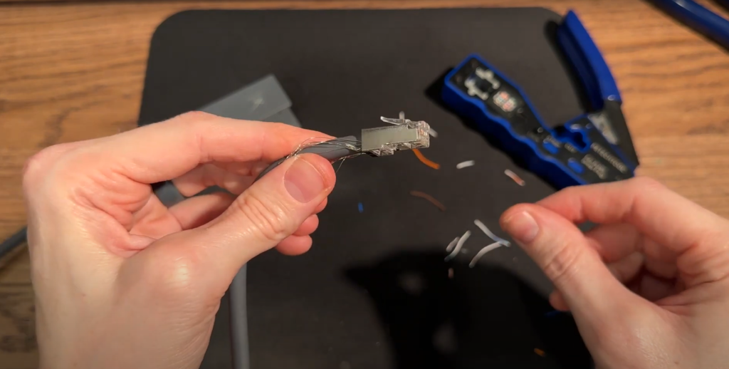
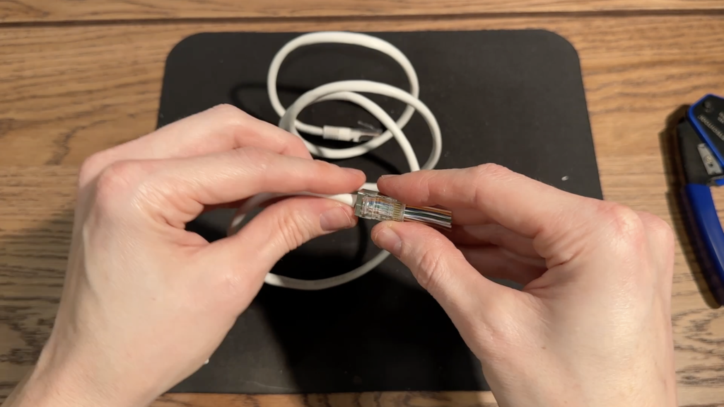
Keep holding the wires with your left thumb and index finger. With all 8 conductors in the correct order, flat, and straightened out, make a flush cut across all the wires with wire cutters, taking off about a half inch. With a clean, straight end, now take your RJ45 connector and insert it onto the wires. Tab side down! After you do this, triple check that the wires are still in the correct order. As you hold the cable in your left hand, the order from top to bottom should be: White/Orange, Orange, Blue, White/Green, Green, White/Blue, White/Brown, Brown.
The foil and drain wire should be folded back along the cable at this point. Slide the RJ45 connector back so that as much of the cable jacket, foil, and drain wire are inserted into the connector as possible. Then, use your crimp tool to crimp down on the RJ45 connector to terminate the cable. Trim off any excess wire that remains. Also trim off any foil and drain wire that extends out past the connector.
Step 2 – Build The Power Supply

Mounting Method
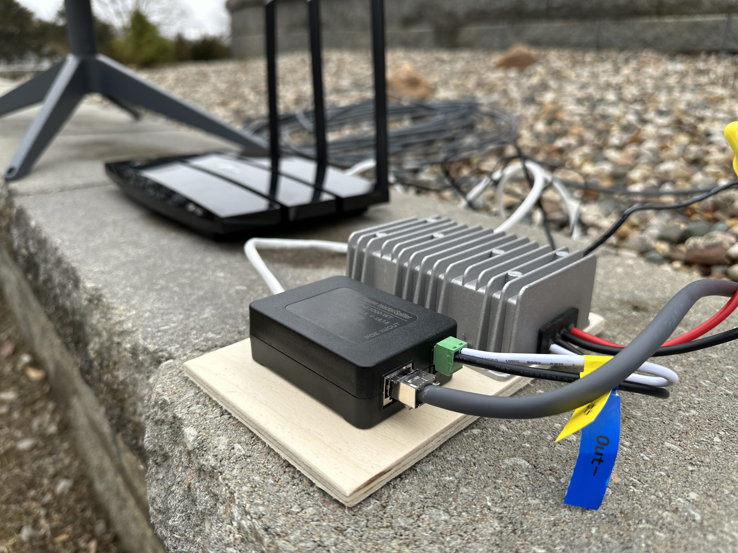
In this tutorial, I’m just building the power supply by screwing the components to a scrap piece of wood. For your own power supply, get creative if you want. I’m just using wood screws to secure the POE injector and DC-DC converter to the wood. Eventually, I’ll mount this in my RV in a utility cabinet.
Assemble The Components
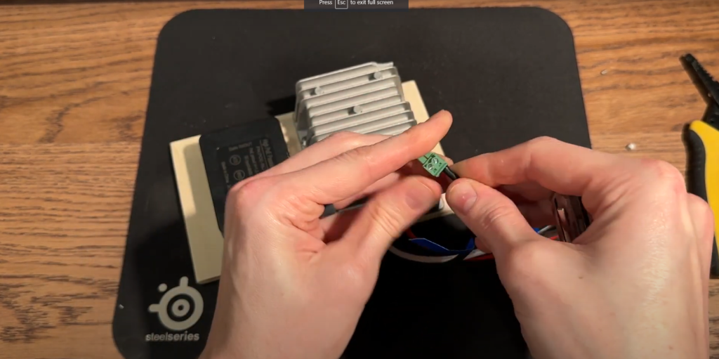

First, take a look at the DC-DC power converter wires. They should be labeled for voltage in and voltage out. The voltage input wires, red (positive) and black (negative), will hook to your battery system. We can set these wires aside for this tutorial. Identify the voltage output wires. White for positive, black for negative.
Route the voltage output wires into the DC input of the POE injector, making sure to match white to positive, and black to negative. You may need to strip about 1/4 inch of insulation off the wire if it doesn’t already come stripped. Use a screwdriver to secure the exposed part of the wire into the terminal, double checking that you have the correct polarity.
At this point, the power supply part of this project is complete. Like I mentioned before, the two other wires on the DC-DC converter connect to your battery system. How that looks depends on your individual application, so you’ll need to figure out the best way to supply DC voltage from your battery to your Starlink DC power supply. In my case, I have a fuse block in my RV with an unused slot. I ran some wire from the fuse block to where my power supply will mounted. Then, I connected the wires with butt splices. I went ahead and removed the fuse beforehand, so that power is not being applied to my project until I’m ready to test.
Remember, practice electrical safety! Don't hook up to your battery until you are ready to test! Please consult an electrician if you are not comfortable and knowledgeable working with your RV/cabin/van/etc. electrical system.
Step 3 – Modify The Router Cables
Before we begin to modify any of the router cables, it’s a good idea to go through the router setup and configuration. It’s just easier to do this now rather than worrying about it later. The specifics will depend on your router model, but follow the manufacturer instructions for how to perform the initial setup. You should set up a Wifi name and password on your router before continuing, so that when it comes time to test your power supply, you can connect and test it right away.
Router Ethernet Cable
Next we need to reconfigure one end of an Ethernet cable. This cable will be what we plug our router into the POE injector with. Remember how I said the Starlink POE pinout is different? Since we had to modify the dish side of the connector, we also need to modify the router side connector to match. We only have to modify the end that plugs into the POE injector, not both ends. Your aftermarket router probably came with an Ethernet cable that you can use. Otherwise, you can find a 6ft, 12ft, etc. Ethernet cable at any electronics or home store.
Repeat the process that we used in Step 1 on just one end of the Ethernet cable. The pinout will be the same. The Ethernet cable won’t be shielded, so it won’t have the foil or the drain line conductor. But you can still use the shielded RJ45 connectors, no worries there. The modified RJ45 connector end of the Ethernet cable plugs into the POE injector. The other end of the Ethernet cable plugs into the Wifi router.
Router Power Supply
Most Wifi routers, including the one example in the supplies list in this article, run off DC. The power cord has an AC to DC converter built into the part that plugs into the wall. If you are using a different router, it might have a power brick that sits in between the wall plug and the router. Since we want the router to be powered only by DC, we can simply cut the wire after the power brick, so that we can utilize the same DC power connector that comes with the router.
For the TP-Link router I’m using, the wire with the white strip is positive, and the one without is negative. Verify the polarity for your router if you are using a different one. Connecting to a DC power source with the wires reversed can result in damage to the router!
Now we just need to connect the 12V battery system to the power wire from router. In my case, I ran a wire from my RV fuse block to the router location. That gives me 12V DC power, and I just connected the wires with butt splices. I’m mounting my router in the same location as my power supply, so routing the Ethernet cable that connects the router to the POE injector isn’t difficult. If you are going to mount the router in a different location, you will need to plan how to route the Ethernet cable back to your new Starlink DC power supply.
Step 4 – Plug Everything In

At this point in the process, all of the following should be completed:
- An RJ45 connector has replaced the Starlink connector on the Ethernet Adapter (or Starlink cable)
- The output from the DC-DC converter has been connected to the input of the POE injector
- The Ethernet cable from the router to the POE injector has a new RJ45 connector on one end that is using the modified pinout shown in the previous section
- The router power supply has been modified to wire into the battery system of your application
Apply Battery Power
If all of the above is done, now we can test it out! Apply battery power to the input of the DC-DC converter, in whatever way you have decided to hook it up. In my case, I just need to reinsert the fuse on my RV fuse block to apply power to my Starlink DC power supply.
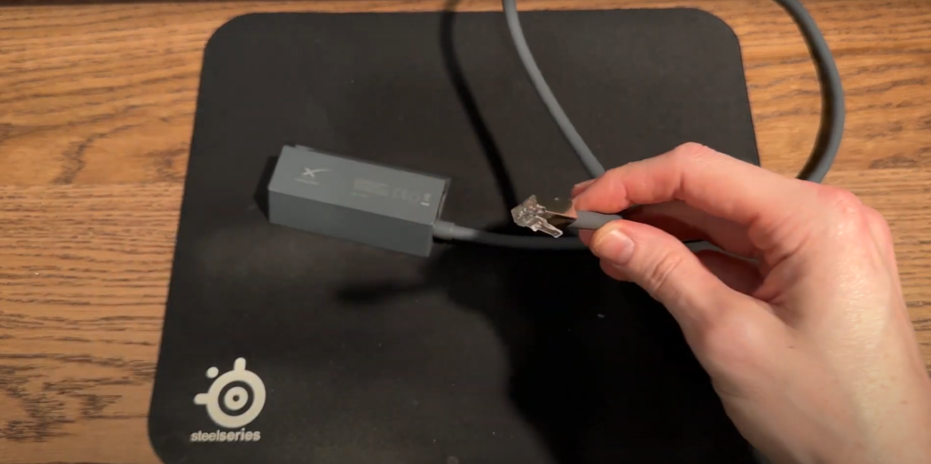
Connect The Dish And Ethernet Adapter
If you are using the Ethernet Adapter in this tutorial, plug the Starlink dish cable into the Ethernet Adapter. Then, plug in the modified RJ45 connector on your Starlink Ethernet Adapter (or Starlink cable) to the power POE port on the POE injector.
Plug In The Router
Next, make the connections on the router. There should be an Ethernet cable connecting from the data port on the POE injector to the WAN or Internet port on the router. Also, plug in the router power supply to DC power. Verify that the router turns on. If you didn’t already go through the router setup before, now is a good time to do it. You’ll have to reference the instructions for your particular router.
Test The DC Power Supply
Whether you chose the easy way or the cheap way, your power supply should be built at this point. Everything should be hooked up and ready to test.
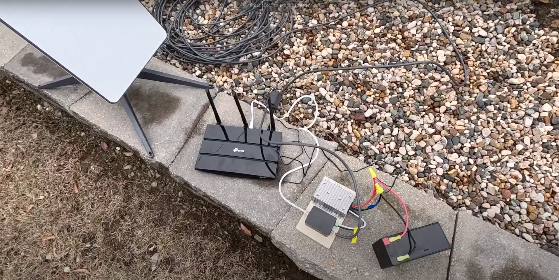
Set up your Starlink dish nearby with a clear view of the sky. The first thing to check is your aftermarket router. Make sure it’s powered on and broadcasting a Wifi signal. Grab your phone and connect to the Wifi network of your router.
Check to make sure that the Starlink dish is powered on. There are no LED’s or indicators, but the dish should move itself into a vertical position within a several minutes of power being applied to the Starlink cable. It searches for satellites in the vertical position, and then it will aim itself in its ideal direction. You can verify the dish is on by opening the Starlink app on your phone (your phone needs to be connected to the router Wifi network). Alternatively, you can use an internet browser on a device connected to your Wifi network and browse to http://dishy.starlink.com/
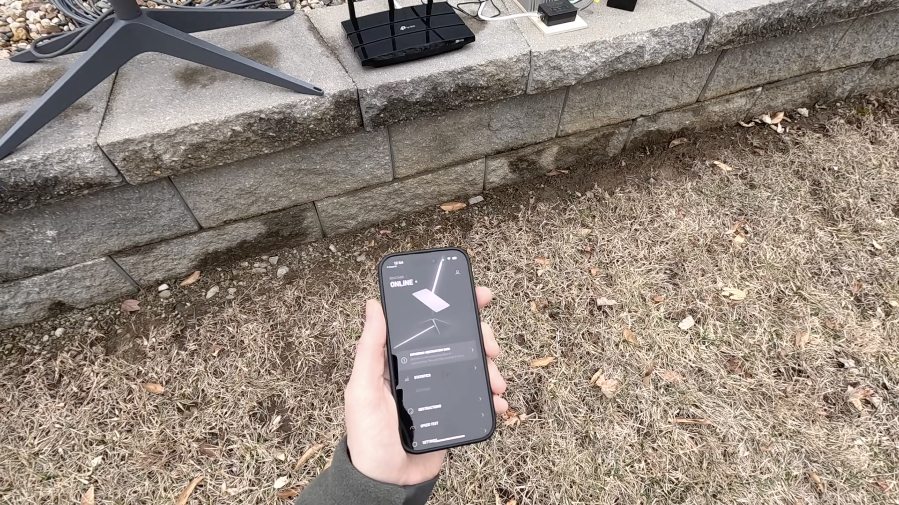
It may take up to 10-15 minutes for the dish to boot up and become available to view on the app or website. The app will let you know if the dish is working or not. If you have an active subscription, the status should change to Online after several minutes of booting up and searching for satellites. Check for internet connectivity by performing a speed test. Speeds with this setup should be similar to what you get with a normal setup.
I was able to connect using my TP-Link router right away. If the Starlink app keeps saying Disconnected, even though your setup is working with internet, you might need to create a static route to the dish.
The Results
I tested my new Starlink 12V DC power supply for about an hour to verify that it stayed connected to the internet. I performed several speed tests, watched a video, and checked email. I kept an eye on my battery monitor (I’m using the EcoFlow River 2 portable power station) throughout the testing to check power usage.
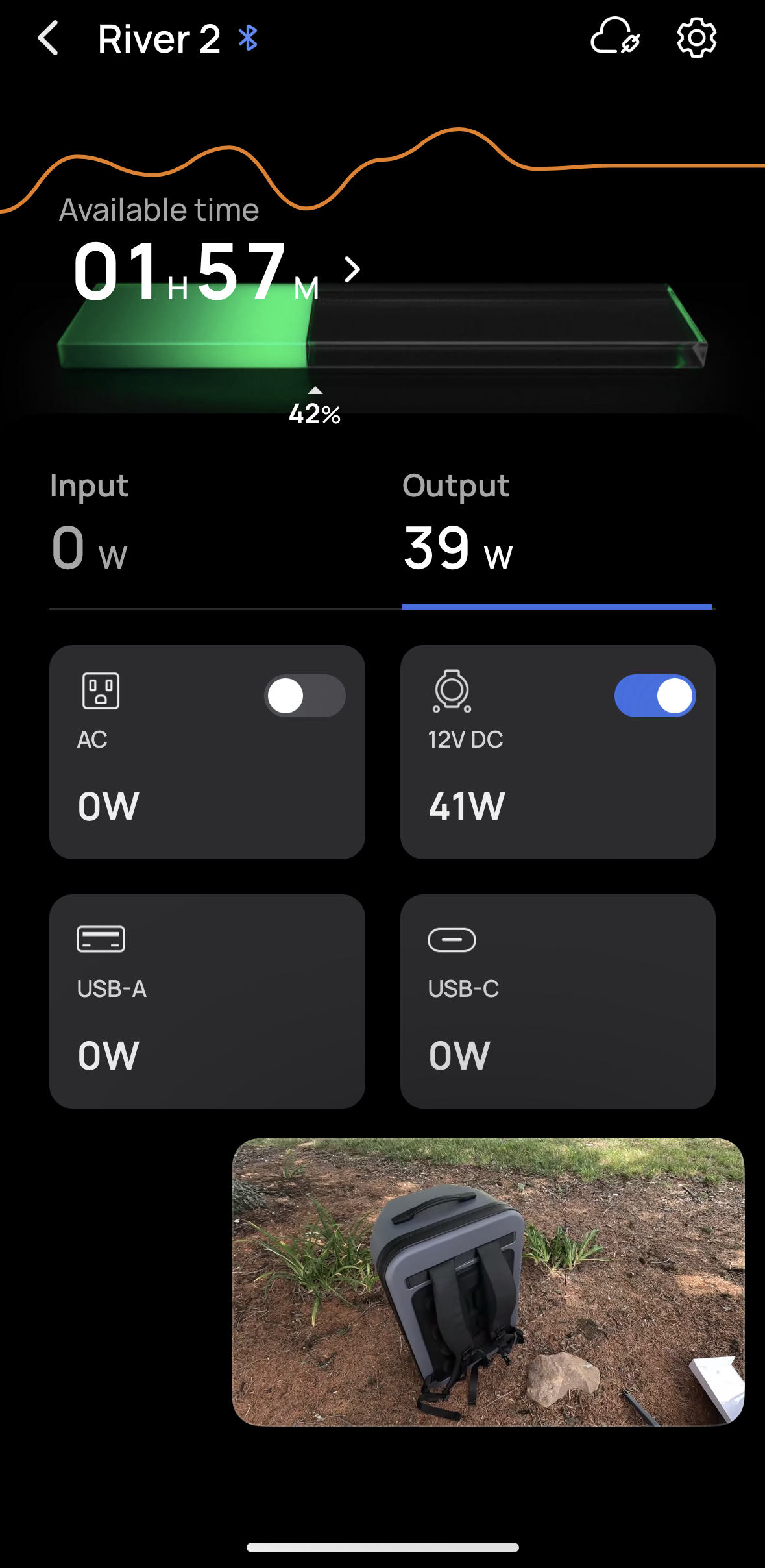
As you can see from the screenshot above, the power supply was drawing around 40 watts while streaming a 1080p YouTube video. The 40 watts includes the power needed for the dish, as well as the Wifi router.
Now take a look at how much power the same Starlink dish uses when plugged into AC power via the Starlink router. I streamed the same 1080p YouTube video for this test as well, so that the comparison was as fair as possible.

I consistently saw about 45-50 watts when streaming the YouTube video on AC power. This wasn’t a scientific test, but I think it’s safe to say I saw a roughly 15% reduction in power when using DC power, compared to using the Starlink router and AC power.
Saving 7 watts might not seem like a big deal. For people connected to the grid, it really isn’t much. But for those of us trying to use Starlink off-grid, 7 watts is pretty significant when you think about hours and hours of use each day. Even if I were to be conservative, and call it a 10% improvement by powering Starlink from DC, I call that a success.
Final Thoughts
This isn’t the easiest project to do, especially if you chose the cheaper method involving cutting the Starlink cable. If you decide to tackle this yourself, I hope you find this guide helpful. As you found out by reading, I was able to improve my energy usage by about 15% by building my own DC power supply to run off 12V.
Just make sure to exercise caution when working with electricity. And also keep in mind that modifying how your dish is powered can result in damage that won’t be covered under your warranty. With all that said, let me know if you have any feedback or questions in the comments below!
hi, system works great on a battery, but when i wire it up in motorhome it will not go online. the synology router wan connection keeps going on and off as the router is booting so dosnt go online. theres 48.1v at the converter but my supply is 13.1 volts, 14.2 volts when charging. i cant work out if the router is too voltage sensitive, or the converter as the amps to the dish keep rising to 6 and falling again several times before settling at 0.9 and the router occasionally boots fully, but i cant connect to dish with starlink app.
ive tried it with starlink router on 240v perfect . ive got it running on 12v from my test battery now, perfect, do you have a suggestion where my problem lies .
brilliant, the system is running great, the synology router works great but im still getting router disconnected in the starlink advanced page. ive set a static route in router but no different, ive read online all sorts of options for the static route. do you have settings you know work you could pass on to try
cheer
hi, just got all the bits together, but a quick question, how much current does the converter draw from the 12v batteries to run the system ?. the cables on the converter are 6mm2 but would be easier to run thru van in something lighter. i see it uses 40 watts at the dish end but cant find info about the supply
cheers, ill report back when it all works
The power supply is rated at 8 amps, so I would use whatever fuse rating you have on the DC circuit to determine your wiring. For example, I’m using a 10A fuse on the circuit, so I would plan all the wiring to handle up to 10A. You could do 8A as well, but I wouldn’t go below what the supply is rated at, even though it won’t be using anywhere near that most of the time.
thank you. ill get the wiring for 10 amp and a fuse. i see you haven’t used the earth connector on the poe injector. i take it that’s not required.
great write up and easy to follow thanks
brilliant, the system is running great, the synology router works great but im still getting router disconnected in the starlink advanced page. ive set a static route in router but no different, ive read online all sorts of options for the static route. do you have settings you know work you could pass on to try
cheer
ive got the bits but i cant see what amps the converter takes from the 12v battery side, it has hefty leads on it 6mm i think, but if theres no need for that gauge to run through the van i can get smaller
Supply is rated at 8A.
Any updates on your Gen 3 system? Looking at the new setup, the dish must be PoE (I suspect 802.3bt Type 4). Since the output of the Gen 3 router brick is 57V @ 3.42A (195W) a 12v-57v Step up should work. Now the only question is, what is the pinout for the PoE? The supplied Starlink cable (dish to router direct) is a standard shielded patch cable so the only thing left would be a non-standard pinout on the router itself. Since the diagrams show you can connect the Gen 3 router to a Gen 2 dish (with the attached ethernet adapter) it would seem the pinout would be standard. This Step-Up/Injector should work if that is the case.
Yes, so I’ve tried the Gen 3 conversion method that is floating around online. It involves a cheap Amazon DC-DC converter rated at 56V and 3 amps. You just combine that with a DC barrel plug, and plug directly into the Gen 3 router. Simple setup for DC, however, I can’t get mine to work. The cheap Amazon power supplies have too much ripple on the output, and this causes the dish to go through the boot cycle over and over again. Some have added a capacitor to the output to smooth things out, but that didn’t work for me either. I’m not going to recommend that to my readers, so I’ve sourced another kind of DC converter that I hope will have a more stable output. I will get that tomorrow, and I’m hoping it works so I can finish up my Gen 3 DC tutorial. Although my tutorial will use the existing Gen 3 router, you can also use any 3rd party POE injector to completely cut out the Starlink router if you wish. I don’t think most people care to do that, so I’m aiming my DC conversion for cost and simplicity. I will mention POE injectors, though.
Does Starlink offer a 12 volt power brick for their gen 3 dish that can be used instead of the 125 volt power supply?
No, not at this time.
I purchased a 12v ready built kit from Starmount Systems. Unluckily the unit seems defective and Starmount refuses to even answer my calls. It seems that the 12v step up converter is the problem. I had it tested and the technician says it has a dead short. Is it possible to purchase this as I don’t want to start from scratch.
I’m not sure how their system is designed, but you can purchase the 12v step up converter linked in the article for the Gen 2 dish, as long as you have a POE injector that you can plug it into to power the dish.
Outstanding how-to on DC conversion. Found your site searching for RV use, getting ready to opt for the service.
I already have a Xantrex pure-sine inverter in my RV, and LFP battery with 600W of solar, so I may just try running it on that and see how it does. If it’s a power hog will surely be looking to convert it.
Thank you for your contribution to the technology – you have better information on the service than they do. 😉
Thank you, I appreciate the feedback! Still waiting for a new product to use on the Gen 3 version of this guide. If you are in the US, that’s the model you will be getting. I hear it’s a bit more efficient in terms of the AC-DC conversion, so I’m confident that running it on the inverter will work fine for now. I’m interested to see how much I can gain in terms of efficiency when I build the DC power supply for it.
I just bought the Gen 3 system and want to do a 12v conversion for my RV. I’m wondering if the 48v converter/power booster will work for this system or if I need something like a 12v-56v c/pb as hinted at in a few other posts. Do you know?
Gen 3 runs on 57VDC, so you will need a step up converter that goes to 56V for it to run properly.
Thanks. Yes, I got a 12 > 56v step-up converter. I tested it w/the other items here, and Starlink worked fine. Nice that the dish cable is now RJ-45 and that you don’t need to buy that adapter any longer.
Only question now is how much more efficient is the 12v system than the standard setup.
Thanks. Yes. I got a 12 > 56v step up converter and Starlink runs great! Nice that the dish cable is now RJ-45 and so it’s not necessary to buy that adapter.
:>/
What is the size of the board your used in the “Easy Way”?
I believe it was just a couple of 1×3 boards screwed together. Total surface area ended up being 5″ x 10″.
This is a great project, for a Gen 2 system it seems. Now that the Gen 3 are the default system, is the adaptation to a 12V power source easier? Looks like it would be just a matter of a DC-DC 12-48V block with cable and correct connector to fit the power input on the Starlink router. Is the connector a proprietory part, or is it a standard connector?
The conversion should be easier, but the tough part is finding a decent 12-56V step up converter. The Gen 3 dish runs on 57VDC. The connector on Gen 3 is Standard RJ45, meaning the dish can plug right into a POE supply, no adapter or splicing needed.
So in my reading of this comment the easy 12v conversion shown above will not work with the Sen 3 Starlink hardware. Is this correct?
Correct, only compatible with Gen 2. I’m working on the 12V system for Gen 3, but it isn’t ready to publish yet.
Any updates on your Gen 3 system? Looking at the new setup, the dish must be PoE (I suspect 802.3bt Type 4). Since the output of the Gen 3 router brick is 57V @ 3.42A (195W) a 12v-57v Step up should work. Now the only question is, what is the pinout for the PoE? The supplied Starlink cable (dish to router direct) is a standard shielded patch cable so the only thing left would be a non-standard pinout on the router itself. Since the diagrams show you can connect the Gen 3 router to a Gen 2 dish (with the attached ethernet adapter) it would seem the pinout would be standard. This Step-Up/Injector should work if that is the case. https://www.amazon.com/Elenzk-Industrial-Injector-Hardened-IEEE802-3at/dp/B07V2YD8GR/ref=sr_1_12_sspa?crid=6YZETUCS4XVJ&dib=eyJ2IjoiMSJ9.FZWYshPgy5FIz2U8BP9B2YlCTfIYlpI_aAFTWHq7cGfaQsyyJa4W0181egHkiUnEWrfJyevTbnTQUJAGYh_1E15_P3IoHYVOv1YFPO_gdWVUXs-in_uzCmDwfa2Yz0IGoDfAFShW6lAWGDygb1Io7I1H2fH3nYQ_453eIkIFeh4kHufQC4b2jOK3EGWfadoajGpIGEE5bkWNx-k2EuEG7OaIzjZMS8dZT7ILPLHcXUE.sqYs8UJ2xo98fYSfaHnpRznlbIie3ibQWM6rPYMw_lg&dib_tag=se&keywords=802.3bt%2Binjector&qid=1711132935&sprefix=802.3bt%2Binjector%2Caps%2C105&sr=8-12-spons&sp_csd=d2lkZ2V0TmFtZT1zcF9tdGY&th=1
(A little spendy, but all in one)
Yes, so I’ve tried the Gen 3 conversion method that is floating around online. It involves a cheap Amazon DC-DC converter rated at 56V and 3 amps. You just combine that with a DC barrel plug, and plug directly into the Gen 3 router. Simple setup for DC, however, I can’t get mine to work. The cheap Amazon power supplies have too much ripple on the output, and this causes the dish to go through the boot cycle over and over again. Some have added a capacitor to the output to smooth things out, but that didn’t work for me either. I’m not going to recommend that to my readers, so I’ve sourced another kind of DC converter that I hope will have a more stable output. I will get that tomorrow, and I’m hoping it works so I can finish up my Gen 3 DC tutorial. Although my tutorial will use the existing Gen 3 router, you can also use any 3rd party POE injector to completely cut out the Starlink router if you wish. I don’t think most people care to do that, so I’m aiming my DC conversion for cost and simplicity. I will mention POE injectors, though.
I have a modified version of your simple setup on my boat, and we lost power last night and I think there was a power surge when the batteries took over the load from the AC battery charger (or vice versa), as we had a blown 5amp fuse in the morning and no internet. Question is, should I be using a bigger fuse? I put a 30AMP one back, but wonder if this isn’t a potentially bigger issue.
I recommend a 10A fuse for the 12V supply. The Gen 2 dish can draw up to around 100 watts during startup, or when heating mode is on auto or pre-heat. At 12V, a 5A fuse only allows up to about 60 watts of power draw before the fuse blows. 60 watts is plenty most of the time, but under some conditions, Gen 2 will use more than that.
Thanks for the excellent write-up. I’m on a sailboat, and want to use a Victron 12v-48v converter (to integrate with the other Victron equipment we already use). So in terms of sizing the 12v-48v converter, how many watts does your set-up require, if you know? The Uxcell DC 12V Step-Up to DC 48V Car Power Supply you linked to is rated for 384 watts, just wondering if I would need that much capacity….
The Gen 2 dish uses up to about 100 watts. If you use a quality DC converter, like the Victron, size it based on 100 watts. If they have 125 or 150 watts as an option, that gives you some wiggle room in case the dish has any spikes.
The router you suggested — TP-Link AC1750 Smart WiFi Router, which had a 110v plugin converter to 12volts,— fried almost immediately when I wired it directly to my boat’s (nominal) 12v system. I couldn’t find any specs online as to the voltage tolerance range of the TP-Link, but my theory is that it couldn’t handle the 13.7volts that our boat’s DC system is usually resting at (and it could be even higher when the engine is running!). So second time around, I ordered a GL.iNet GL-SFT1200 (Opal) Secure Travel WiFi Router, which is much smaller and gets powered via a standard USB-C plug (I already have a number of 12V to USB outlet wired into the boat). Worked a charm.
It will fry the router if the polarity is reversed when you wire up the supply. Don’t ask me how I found that out! Hint: I learned the hard way lol. If polarity was correct it may have just been the router itself, I run it off 13-14V all the time in my travel trailer. It is a cheaper model router, I guess the components are a bit weaker and more sensitive.
Hi! I’m planning to use the GL.iNet GL-AXT1800 (Slate AX) on my camper. I’ll use the first option because I don’t want to cut the Starlink cable. My question is, would this work straightforwardly, or would I need to do anything extra? I mean, I’ll connect the router through USB and that’s it.
Thanks in advance for your help!
Great write up! Sorry if this has been mentioned somewhere already in the comments, but does this work for the flat high performance dishys as well? Has anyone tested this type of set up in remote or marine environments? We are putting one of these dishys out in the middle of the ocean and want to minimize power draw without sacrificing satellite connectivity?
To my knowledge, nobody has done the Flat High Performance version and shared it online. My guess is that people avoid the FHP dish because it uses nearly triple the power on the Standard Actuated Gen 2 dish. People interesting in saving every watt will not pick the FHP to begin with.
Just wanted to share that I’m having trouble while testing installation of the Yaosheng POE injector and the RJ45 adapter for Dishy (Starlink) adapter – I keep getting momentary “Disconnected” messages from the Starlink app. Everything works fine with the original Starlink router.
I’m supplying it power with this 12V to 48V 6 amp power converter and I’ve verified that it’s delivering 48V and typically around 3 amps (with some momentary fluctuation higher): https://www.amazon.com/Converter-EAGWELL-Regulator-Adapter-Vehicle/dp/B0B7WZGCM3/
I see that you’ve been recommending the 8A version instead. I bought this 6A version following advice from other sources.
I wrote to the Yaosheng manufacturer and they responded with the explanation that these “cheap” DC step up converters are not suitable/reliable for this. That seems odd given that others have been doing this successfully. However, I have now seen comments in multiple places about these converters being electrically noisy and affecting performance. Yaosheng and others are recommending using the Mean Well DDR-120A-48 step up converter. Notably, it’s only 120 watts vs the 288 watt Eagwell version but others around the web are saying it addressed their issues with the Eagwell power adapters.
I’ve posted the details and the full response from Yaosheng in these reddit posts:
https://www.reddit.com/r/Starlink/comments/18kbqyh
(Of possible interest, note that they’re now making an integrated power converter and POE injector, also only 120 watts.)
I’ve ordered the Mean Well power converter and will try that next. If that doesn’t work I’ll have to go back to Yaosheng to push for a replacement. It’s annoying since I’m well past the Amazon return window for these other components.
Anyway, I’m curious if anyone else has experienced these brief but frequent “Disconnected” messages when trying to use this setup?
Interesting, thanks for the report. My original power supply that is linked in the article is still working fine, I haven’t experience those issues. You’ll have to follow up when you get the Mean Well converter and let us know if it fixed the issue. I’ll consider recommending that one instead, it seems like there are issues with these cheap Amazon power supplies.
I’m also working on a Gen 3 DC power supply, which should be a lot simpler than Gen 2.
Noah, great write-up, thanks! When do you expect to share more about the Gen 3 DC power supply? (Just subscribed to your newsletter so assuming you’ll share there?)
I’m still working through all the Gen 3 tutorials (setup, aiming, review, etc) so it will be after that. And yes, I will make sure to let you know about any new tutorials via the newsletter.
I dove in and ordered parts as listed here to build the easy 12v power system. Reading the cable adapter label fine print it only mentioned Dishy v2 and thought further investigation on V3 compatibility might be warranted before moving forward. Apparently there are some differences, any more info on an 12v conversion for V3 hardware?
The differences are:
– No adapter needed, since the Gen 3 uses RJ45 connectors already
– 56V DC converter needed instead of 48V
Installing the Mean Well power converter didn’t help with my “Disconnected” messages. As I noted in my separate reply below, I finally discovered it only happens with my USB-powered GL-iNet GL-SFT1200 (Opal) router despite that this router works fine when tested separately.
I’ve provided links to more details in that reply just below.
You rock! Thanks for sharing your findings, I’m sure it will help others having this issue in the future. Hopefully GL-iNet is able to figure out why it’s happening.
Hi Christopher, yes, same here. All the same parts, same setup. I am very proficient with 12v setups, and this one baffles me. Swap back to the SL router; all is good. Swap back to 12v and disconnect non-stop. The multimeter shows 48.09-48.39v — but I need to get a POE tester to see what the Yaosheng POE injector out to Dishy reads. Honestly, I have little faith in the Chinese parts (no USA rah rah here – I’m in Australia), but the 12v-48v step-ups from Amazon are a crap shoot and sadly no manufacture of substance (Victron etc.) has 12->48. The Yaosheng POE injector is more promising but still suffers from a lack of faith and belief it’s not the problem, they seem to be on a mission to lock the 12v SL market (until Elon ships a high-priced mobile router) so maybe they will find a means of eliminating their products as the culprit. All said, I’m curious about the Meanwell, given Dishy’s sensitivity to pure smooth 48v. Happy holidays….
I’ve just discovered that my frequent “Disconnected” status in the Starlink app is NOT caused by the Eagwell or Mean Well power converters or the Yaosheng POE injector or cable adapter.
It’s my USB-powered GL-iNet GL-SFT1200 (Opal) router! This router works fine tested separately (and others are using it with Starlink) but when I swapped in an old 120V-powered Asus home router, the Disconnected messages stopped. I’m now going to contact GL-iNet support to try to solve this.
I’ve updated my Reddit thread on this issue:
https://www.reddit.com/r/Starlink/comments/18kbqyh
Searching on GL-iNet and Starlink, I found a couple other folks experiencing this problem and I posted there:
https://www.reddit.com/r/VanLife/comments/17v8m0d/help_needed_intermittent_starlink_disconnect_when/
After a couple weeks of working with Gl.iNet support and engineering doing remote testing, they eventually noticed that the router is seeing a changing MAC address (we don’t know why) and they found a workaround.
Short answer:
Turn off the “Network Acceleration” option under Network settings. No more disconnects for me.
Longer answer here:
https://www.reddit.com/r/Starlink/comments/18kbqyh/comment/kuli9hh/
I have a question about using the YAOSHENG PoE Injector. In your really great tutorial and video, you’re using a 48V/8A DC to DC converter. But the injector clearly states that it is only rated for 3A (150W). And your test results match that. Your roughly 40W of usage on your power station converts to 3.33A at 12V, you subtract out the 1.5A max load of the router, and you’re well under 3A of usage. (Not that I think the router is pulling that much power.)
I’m seeing posts around the internet of short runs at 175W of draw during startup. (I’m sure this doesn’t include the heater function usage as well). Is it possible that by allowing more amperage to be available from the high amperage converter, the failures people are getting are actually due to them slowly burning out the injector? Which also possibly is not rated for the full power requirements of the dishy (if it’s actually drawing 175W)?
Just out of curiosity, your own blog states average 50-75W, so I wonder why you feel the 8A converter is necessary? I remember seeing somewhere that you thought 6A was borderline. But that’s 288W. Almost double the specified amperage for the injector.
If you really need those extra watts, then it really seems that the YAOSHENG really isn’t a good option. Even though it is a very elegant option.
Thanks for the great tutorial, I’m just trying to sort out the numbers before I move mine off the inverter.
The Gen 2 dish can use up to about 100 watts at some points during startup, or if the dish is in heating mode. I recommend the higher amp power supply to give some headroom for these high power events, as well as because these cheap components don’t have the tightest quality control or specifications. In other words, I’d rather be using a power supply rated for 8A, and only using a few amps from it, than trying to use a 3A power supply and constantly asking 3 amps out of it.
OK I have the cheaper setup installed, I get an IP address, but cannot connect.
What am I doing wrong?
I have everything mounted the way you recommed, and using the TP Link router.
Cannot connect to the internet, or can’t see the Starlink status in the app? From what readers have shared, the POE injector seems to be the thing that fails the most in the cheap setup. If you have spare connectors, I would try to re-crimp everything. Also triple check the pinouts are correct. Do you measure 48V on the output of the DC-DC converter?
Great write up! Thank you! I built a “easy” version 12v dc power supply using the yaosheng POE injector and dishy adapter you specified. But in order to simplify setting up my statlink on my slide in truck camper I am going to cut my starlink cable and run it through the camper wall using a shielded rj45 female-female connector. I have two questions.
First, Do I understand correctly from an answer you provided to another comment that I can use a standard pinout through the rj 45 connector?
Second, if I use the modified RJ45 pinout like in the “cheap” version on the end of the cable where it plugs into the power supply can I plug this end directly into the yaosheng POE injector and abandon the yaosheng dishy v2 adapter ? As long as I bought (using your links) the tools and supplies to cut the cable and attach rj45 connectors I figure I could abandon the adapter and make my power supply a little more compact.
For the camper wall connector, wire all connectors using the standard T568b pinout. This is just a “straight through” connection, no swapping pairs needed. If you are using the Yaosheng POE injector, you won’t need to use the modified pinout at all. The POE injector does it for you. So on the end that goes to the POE, just wire that as T568b as well. You are correct that you don’t need the adapter, it’s just nice if you don’t want to have to cut the cable at all.
Thank you for the answers! I really appreciate it.
I’m using the Yoasheng components recommended but the step up converter was out of stock so went with a 6amp version. Using the TPLink router. Everything fired up but no internet. Is it necessary to use a CAT6 Ethernet cable between the router and the POE? I just used the cable that came with the router that is not an 8 wire. Could this be the issue?
The cable that came with the router should be an 8 pin Ethernet cable. If it’s not, that would be the issue. CAT5/6 isn’t a problem, as long as it’s a standard 8 conductor Ethernet cable between the router and POE data port.
Hello, great tutorial! Will this work with the round dishy?
This specific tutorial won’t. The round dish uses 56V instead of 48V, and is capable of using more watts. I believe the wiring pinout is the same, though. If you could find a 56V power supply, and a POE injector that can handle 150+ watts, you could make it work.
Oh, that ment there is no solution right? The Problem is the POE injektor? Okay
Hello; The Yaosheng equipment has a VERY high failure rate and even many delivered DOA. Aside from your more difficult method are there any other options similar to the Yaosheng setup but more reliable that you are aware of?
Thanks, Ben
Source on the high failure rates? I haven’t had an issue with the 2 sets I have, and the Amazon reviews from other buyers don’t indicate any obvious failure patterns.
Thanks for the great tutorial! I’ve followed the instructions and have used the “Cheap” approach. I am using the 8A supply, assuming that is not defective but you never know. When I connect via the app or the browser, the starlink is in a constant cycle of Disconnected and Booting. I’ve let it roll for 30 min plus so assuming it’s not something being updated. When I switch back to the starlink router, everything is fine. So it seems there is something in the circuit or configuration. I’m using a TPLink TP750 travel router. Any suggestions? Should I replace the DC-DC power supply? Is this a situation that could be rectified by using the Bypass instructions you’ve suggested (I hate to do this because it means buying another Starlink Ethernet Adapter because the first I bought I cut and added the RJ45 connector). Thanks!
Based on other reports of failures, I would try to return/replace the POE injector first, power supply next if it isn’t the POE injector. But before all that, I would recommend redoing all the connectors just to be sure everything is solid and the correct pinouts.
Awesome, thanks Noah. I’ll try all of it, starting with the connectors.
Any idea if this will work for the Flat HP dish?
It feels like it should, but wondering if anyone has tried it…
This tutorial won’t work for the Flat High Performance.
Noah is there any aftermarket cables that will work with this solution. The ends are different on the HP dish then what you showed in the video. We are installing these on fire apparatus. Any suggestions.
Not that I know of. In fact, I haven’t seen any DC conversions for the HP dish. I think most people just avoid it since it is so power hungry.
We bought all the parts but the starling antenna wires has different ends than shown in the tutorial. Looking for a replacement antenna wire that will connect into the POE injector.
I was trying to modify the cable to use 12V system, but it is pretty strange that sometimes the starlink does not boot up at all.
I test the modified system with variable supply and multimeter, and it is obvious that the network cable is outputing 48V, I even connect a 5V to test the POE function to a camera and it works. But when I connect to starlink and look at the variable supply, 0 current means it does not boot up.
I plug the starlink into 110V and it instantly boot.
Any ideas?
POE injector could be bad. The power supply could not be rated high enough. Starlink will use sometimes around 5A at 12V. Even more if heating is still turned on.
Hey there
I’ve had the setup up and running with 12v using the DC-DC Converter, the Yaosheng POE Injector together with my Teltonika RUTX50 router for around 2 months. But from day to day it stopped working.
On the roof of my camper I have a RJ45 coupler, so in the morning I put up the dish and connect my modified SL cable with a RJ45 to the coupler, that runs over the roof and down to the POE Injector. From the POE Injector I have a cable to the router into the WAN port.
The router LAN is running with 10.10.1.1 fixed and I’m using the DHCP service using addresses from 10.1.1.100 to 10.1.1.200. There should be no conflict with default Starlink IP’s doing this.
The dish seems really fine and startup / stow / unstow moves as expected. The connection into the dish is pushed all the way to the end.
I can not acces the dish using neither http://dishy.starlink.com nor 192.168. 100.1.
I can access the dish using remote connection from the Starlink App, and it’s stated as online. When I use local wifi, then it’s not connected.
I can see in the router interface, that neither WAN nor WAN6 interface gets an IP. I guess one of those are supposed to get an IP, right? The LEDs on the WAN interface on the router are not lit nor blinking.
I’ve inspected all cables and connects. All seems fine.
Any suggestions here?
Thanks in advance!
You might need to create a static route to the dish IP if you can’t get it to connect to the app:
Network destination: 192.168.100.0
Subnet Mask: 255.255.255.0
Gateway: 192.168.100.1
Interface: WAN
Hey
Thanks. Unfortunately it’s not only connecting to the app but also the entire internet connection in general that’s not working.
I made loads of testing yesterday in the end original router with (coupled) cut and rj45’ed cables works, original router in bypass mode + ethernet adaptor works, and poe injector is 56v (fluctating between 46v and 49v when dish is connected), so must be data part of the poe, I guess. No sure how to test poe injector in any other way.
After loads of testing I’ve identified the POE to be the issue as it get generate the power but not the data. So nothing bad on the Teltonika part of this setup at all 🙂
Hi Noah. Thx for detailed explanation of easy setup. I do well with cookbook instructions. 😂 I set up my Starlink system as a “normal” system first, using AC power at house and a third party router to prevent configuration issues later. Then I set up all equipment to test, plugged into my batter, and everything worked fine! I have connectivity and my app shows connected to system. I wanted to test to see if the 12 volt system I have would re-align the dish. So I manually rotated the dish (just by lifting it up by base and turning it). Still have connectivity and all is good. However, the dish has not re-aligned itself to where it was before (facing north). I turned it about 180 degrees. My app said checking for obstructions and will take another 5 hours! Is this normal? Can/should I speed up this process? Many thanks.
Stow the dish using the app, and then un-stow. Or reboot the system. When it powers on, the dish will point straight up, and then align itself within about 15 minutes.
Great article! I went the easy way and bought the Yaosheng adapter and POE injector, with their cable.
I have hooked everything up correctly and it’s not working. I’ve got 48 V coming out of my power supply put the dish just sits there and the router never finds a WAN.
Did she still works perfectly if I use the 110v setup.
Any ideas how I can decipher what’s wrong here?
I’ve also verified there’s power out of the poe interface and it’s cable
Does the dish ever move? Can you access the Starlink app to see what the status says?
The dish never moves and the starlink app doesn’t work, since it’s not connecting up. I also tried a second router and multiple cables, that didn’t work either.
I did stick the WAN cable directly into my laptop instead of the router, and set up a static IP to match the dishy subnet, and could then get directly to the dishy page from there. 192.168.100.1
I even bought a new Starlink to RJ45 unit, thinking maybe I got a defective one. But nope, still no movement or internet. I’m just baffled at this point. Help me, obi wan kenobi. you’re my only hope. 😉
If you used the Yaosheng adapter, and their POE injector, it has to be one of those that is defective. Since there is no cable modification, there is only hardware that could be malfunctioning. I would start with requesting a replacement for the adapter. Even the POE could be defective, even if you measure power coming out.
welp, I must be the only person on earth that this doesn’t work for 😉 I’ve used two POE injectors, and two cable adapters, and two of their cables, with all combinations. Still no dice.
Still works plugging into an inverter, so I guess I’ll stick to that.
Nice write up! If you’re cutting the starlink cable for the cheap method anyway, is there a reason you can’t simply re-terminate the router-end with male CAT-6 and use the stock starlink router?
The only possible WAN connection to the Starlink router is through the proprietary Starlink connector, so you would need to save the connector and patch the cable back together with an RJ45 coupling of some sort.
That’s what I’m thinking. I recently had to repair my cable anyway, so I’ve already got an RJ45 male/female in the mix.
Anyway, excited to get this done and get my starlink ready to roam.
Struggling to find the Yaosheng Starlink adaptor. Showing as unavailable from Amazon with no restock date. Anybody know of any other sources.
Great information! The Yaosheng POE Injector looks great, but pricy. To save a few $$ can you use the Yaosheng Dishy Cable Adapter with the Tycon Systems POE-INJ-1000-WT High PoE 4 Pair Injector you use in the “Cheap Method”?
Yes you can do that. The adapter flips the pairs for you, so just use the included Ethernet cable to connect the POE injector and the adapter. Still need the modified router cable though.
has anyone tried running this set up off of a Cigarette light outlet using an adapter? – just wonding id that would work – thx
I run this setup from a portal power bank, which has a 12V car style outlet that feeds the DC-DC converter. It should work fine as a power source, but you need to check the specs on the car power outlet to see how many amps and watts it can provide. If it is only rated at 12V and 3A or something like that, Starlink will pull too much power and blow a fuse in your car.
If you don’t want to build the DC power supply you could also just buy an inverter that plugs into a car 12V outlet. Again, match the power requirements of the Starlink dish to the inverter, and make sure the car outlet can supply the inverter with enough power.
Greetings, thanks for the guide.
I got the Yaosheng PoE injector and the cable to RJ-45 adapter, and this 12-48VDC, 5A, 240W step up transformer from Amazon: https://amzn.to/3qVrDRj
Hooked it all up with a router and it worked great. Took it on our first camping trip and at some point the Starlink app started reporting the Dishy as being disconnected and offline. After multiple power cycles & experiments I still could not get it to come back. Fortunately I was smart enough to bring the stock Starlink router. After a factory reset I am back online with the stock router, but I’m not really wanting to run my AC inverter all the time.
I suspect the failure occurred after the Dishy decided to turn on its heater. There is a light on the PoE adapter showing that it’s getting power from the transformer. My multimeter reports 12v in, 48v out of the transformer and 48v at the PoE injector. I don’t have any way to measure what’s coming out of the injector or into the RJ-45 to Starlink connector.
Anyone ever seen this before? Ideas for testing what’s wrong? Should I open an RMA with Amazon/Yaosheng? Is there a fuse somewhere that I might have blown?
I recommend the step up converter linked in the article (it is rated at 8A compared to the 5A on the product you linked). Like you mentioned, the heating cycle may have overloaded that power supply. 5A would be cutting it close for heating operation. I suggest keeping that heating setting turned off for DC operation. Amazon makes returns/replacements easy, so I would start with POE injector first since you are getting 48V from the converter.
Would the 6amp still not be enough?
6A would likely work, but it’s right on the limit. It’s best to just use what I have listed, I can’t recommend anything else as I don’t have experience with it.
It looks like you mention that this is for the standard model of starlink. Has anyone tried this with the high performance model designed for rv use?
I haven’t seen a comprehensive DC conversion for the Flat High Performance model yet. I don’t personally own that model at this time. The power consumption is too high for most people, whether running on DC or not. The 50 watts on the Standard antenna is much more battery friendly than 100+ watts for the Flat High Performance.
Thank you for this step by step power conversion. Very helpful! I made some slight changes to my build so that I can use the set up in multiple places, like either my truck, or my camper without having to run the inverter in my truck. I elected to utilize the cable adapter so i can use either this power source, or still use the Starlink gear when I have 110 power available. I added a second deck to the mounting board so I could mount my router and keep everything easily portable and together. I also fed the power for both units with a fused accessory plug that can plug in to the power port of either the camper or the truck. As I use my Starlink on the go and leave it in the truck most of the time, I added a power switch behind the router to easily turn everything on or off as needed without having to unplug it. The whole thing is easily portable and sets on rubber feet. You can see photos of the build at: https://drive.google.com/drive/folders/14wGmUp5IIK0Sbdv9i55wnsMMAAN6Z1Mh?usp=sharing
I had the problem the connection to the Starlink breaks after a few seconds in the app. The reason for that was the TP Link Router always try to get the new “Dynamic IP”. Solution was to set it to “Static”.
My way to ddo that Network -> Internet:
Internet Connection Type: Static IP
IP Address: 192.168.100.100
Subnet Mask: 255.255.255.0
Default Gateway: 192.168.100.1
Primary DNS: 192.168.100.1
Secondary DNS: 192.168.100.1
MTU Size: 1500
Is this still working for you as I cannot get my tplink to connect.
If I plug the Starlink into computer I get assigned an IP and have Internet but the tplink says nothing is plugged in when I use the wan port.
Great tutorial, this has been a lot of fun.
I followed everything for the cheap method (cut the factory cable and put a shielded RJ45 with the wire diagram posted here), BUT I only get 2-5mb download speeds.
Items I used:
ROUTER: GL.iNet GL-SFT1200 (Opal)
POE: Tycon Systems POE-INJ-1000-WT
DC-DC: Eagwell 12v > 48v
Everything powers on and works fine, just slow connections.
I ran it for 6 hours and the Starlink app said I had a great view of the sky, no obstructions.
I took the factory ethernet cable that I cut and the piece I did’t use, the one that used to go to the Starlink router, I crimped on a shielded RJ45 with the same modified Starlink wire diagram from this tutorial. I used an ethernet coupler and coupled this cut wire back together and successfully have 100mb+ download speeds. Same time of day, location, weather situations, everything. Just minutes timing different.
So begins the troubleshooting. I took my TP-link Archer A6 router from my house and tried that with my 12v setup instead of the GL.iNet router above (I just kept the TP-link plugged into 120v AC). Using this router the Starlink app could not see Dishy at all. I really don’t know why this router didn’t seem to work in the 12v setup, yet the GL.iNet did.
I took the short ethernet cable from the POE to the router and put a new RJ45 on that (with the special wire diagram here). No luck. I also put a new RJ45 on the factory Starlink cable, even though I verified that cable works fine when coupled back to the end I chopped off.
I don’t have any other routers, POEs, or DC-DC converters laying around so I thought I’d get suggestions on:
1) did I miss something else?
2) which of the above 3 components would you replace first?
Thanks everyone, this seems like a great community I stumbled upon!
I had the same issue and have found it to be the power supply. I was using a 3A 48V unit but I was getting really poor performance so I tried using a 56V battery from my mower and success, so I am now in the process of ordering a 56V converter.
if I am going straight through a connector , do I need to modiify the pin out on my RJ45 connector?
No, if you are doing a coupler, you can wire it up to T568B.
Is it possible to use lifepo4 battery with 48V setup with actual output of 51.2V to directly power the starlink dish ?
Yes, the POE injector will be able to handle that voltage. Double check specs if you are using different ones than listed in this article.
Amazing writeup. I did the whole thing today. Extensive testing tells me that all voltages are right from inside out. But when I connect the modified data cable from the PoE injector back to my router’s WAN port, I’m getting weirdness. The lights flash for a few seconds, then stop. Wait roughly 20 seconds, and then it happens again. I can’t pull down an IP address on the router console or receive any real confirmation that the Starlink likes what it is getting for power and data.
Here are my notes and verifications of all of the steps: https://docs.google.com/document/d/1ENzy-cqPMf1bwonwPXNrYndVMbRXxI9xzna5bJ_1kKo/edit?usp=sharing
When I hook up the network tester to the data side of the injector, I see the same thing. It might even be grabbing an IP address for a hot second before the connection goes dark again. It almost acts as though Dishy fires up, tries to do something, then decides to power off and wait. I didn’t see the 48VDC cycle like that when monitoring the output of the converter or the injector. The tester’s lights and display can see something happening, it tries to test that connection, but then it goes dark before any real data comes back.
Have you seen Dishy behave this way at all? The only thing I really can’t test is the pin continuity on the modified Starlink cable. I might re-crimp my end as a next step, but I don’t know what else to try at this point.
FWIW, I hooked everything back up to the stock router and got a connection again, so Dishy appears to be unscathed and ready to continue working.
I’ve had several people comment and email me with weird results like this. What they have all boiled down to is defective equipment, usually the POE injector or the power supply. But I would first start with re-crimping everything because that’s pretty easy and cheap to do. Then move on to returning/replacing the components, I would start with the POE injector first.
Thanks for the detailed notes and pictures! I hope you are able to nail down the issue that is preventing your setup from working. I am currently testing some new components for a review, hopefully of higher quality that will be more consistent for people.
I went ahead and ordered a new PoE injector since that seems the flimsiest and it’s the hardest thing for me to test. With my voltmeter on the power supply output pins, I never saw the voltage fluctuate. What I can’t easily do is monitor the voltage and current draw once the Starlink tries to fire up.
Instead of relying on a Linksys router that can be finicky to configure, I hooked up a wired laptop to the data port and set a fixed IP. I added a screenshot and this paragraph to my notes doc I linked above:
I didn’t try recrimping the Starlink cable yet, but I’ll probably do that tomorrow while I’m waiting for the new injector to arrive.
Ugh! My bench power supply couldn’t handle the amps needed. When I put my ammeter in series with the circuit, I could see it ramp up and then drop to nothing. When Dishy tried to spin up its motors, it was starved for power and then stopped.
I switched to an old battery charger (which I should have used from the start), and everything worked. I ran some wire to some unused fuse blocks on the camper, and we are in business. Just in case, I ran it in two circuits so the router gets one 15A path, and the step-up/injector/Dishy combo gets the other.
Thanks again for this amazing tutorial and for the troubleshooting thoughts.
Hey Noah,
First off, thanks for taking the time to make the instructions and answer questions.
Secondly I was hoping you could help with an issue I have encountered. I bought an Active POE injector and I see now that you have used a passive injector. Is there anyway to make the active injector work with starlink? Currently I think that the injector is not getting the “handshake” from the dish and wondering if there is a workaround?
Any feedback would be greatly appreciated.
A lot of the active POE injectors can’t output enough watts for Starlink, which is why most avoid them. But it should still work assuming the voltage and wattage are acceptable. You will need to modify the RJ45 pinout on the Starlink cable to get it to work right with the POE injector.
I did everything as described in this tutorial but starlink not powering up.
I have the POE PN INJ 1000-WT
I have the 12v to 48v converter EAGWELL 288W DC-DC
I have swapped the wires from the starlink cable to the ethernet connector connected to the POE port.
Orange White 1
Orange 2
Blue 3
Greeen white 4
Green 5
Blue white 6
Brown white 7
Brown 8
I have swapped the wires on the Ethernet cable going from the data port on the Poe to the t568b wired cable going to my router. So this cable is t568b on one end and swapped on the other, with the t568b end on the router and the swapped end into the Poe data port.
The voltage is correct on the pins coming out of the Poe
+ on pins 1,2,4,5 – on pin 3,6,7,8
And they are all 48.29 volts
When I connect to the Poe the starlink does not power up, does not try to align, nothing.
The wan is connected to my pepwave router and says no cable connected.
When I connect with my regular cable again, everything works fine.
I modified my starlink cable with Ethernet connectors weeks ago and connect the pieces together with shielded waterproof connectors so I could run the cable into my rv.
That has worked perfect and still works perfect. When I originally did this I made sure I did the cables swapped because I knew I was going to be doing this dc conversion.
I just don’t know why the starlink wont power up even thought the correct voltage is coming out each pin. I have waited as long as 30 min and no movement on the starlink antenna and does not connect to my router.
Is there something wrong with my poe?
Any Ideas?
Same issue for me 🙁 Hope someone can help
So when you added the waterproof Ethernet connector to your RV, did you wire that up to T586B, or the modified pinout? The connectors going through the RV exterior would be wired up to the standard T586B. Only the ends plugging into the POE injector are swapped from T586B.
Other than that, I’m not sure, it sounds like you’ve done everything correctly. If it were me, I would triple check everything, and then move on to returning and replacing all the components.
I finally got it it working, turned out to be a wonky loose Ethernet connector on the power side of the poe. Cheap Chinese construction. I stretched out the pins that push on the connector from the side and there’s kept it from having a bad connection.
Awesome, glad you got it working and figured out the problem. Good information for others in the future as well. Sometimes these issues can be difficult to troubleshoot, so thank you for the follow up.
Your tutorial is excellent!
That said, I followed it to a ‘T’ and something isn’t right in River City. I chose the same parts, but skipped the Starlink Ethernet product, as my ultimate plan will be to put an Ethernet plug on the outside of the trailer.
I know the Starlink dish is getting power because I intentionally put it in Stow mode before powering it up on the new configuration. It was my best way to know it was working. Sure enough, it ‘moved’ and it aligned to the correct direction based upon previous experience.
I know the Router works because I configured it in advance. It gets power. It just doesn’t see anyone home on the Internet side of things.
The Starlink app doesn’t see the Starlink even though I’m on the new router. Nor does the router see anything. Yes, I rewired the Ethernet from the Router to the POE product. Yes, I wired the end of the Starlink cable that goes into the POE. Yes, they go into the right ports on the POE (or else the Starlink would get it’s precious 48V).
So what’s next? I moved the Starlink back to its OEM router (with my unadulterated cable) and it works great! Seems like the Starlink is functional. Seems the 12V to 48V is functional. Seems the POE device is functional. Seems the Router is functional.
But someone isn’t talking the same language to each other. Ideas?
Try a factory reset on the new router. Also try to create a static route to the Starlink dish IP address:
Network destination: 192.168.100.0
Subnet Mask: 255.255.255.0
Gateway: 192.168.100.1
Interface: WAN
Great suggestions, Noah. I had already upgraded the firmware on the TP-Link AX1800, tried a factory reset, tried exactly that static route above, and even tried Bypass mode on the Starlink. None worked.
I reconnected the Starlink back to its own router and factory reset it (to get out of Bypass mode).
Then I had an epiphany. In the house, I have a Google Wifi router. So I took it outside and plugged the Starlink back into the POE device, plugged the Google router in, and it WORKED. Nothing needed. No Bypass mode, nothing. (It’s really slow, but it worked)
Why did one router work as described in your tutorial and another one, brand new, doesn’t? TP-Link is a good product, so it seems odd.
New New discovery. I got the TP-Link router to work if I set the negotiation speed to 10mbs Half Duplex. The auto-setting (up to 1000mbps) didn’t work and none of the others worked either. This speed Sucks! I’m getting 7 down and 5 up! Why in the world wouldn’t the higher rates function in this router?
That is odd, not sure on that one, but glad you got it working with another router!
First of all I want to say thanks Noah for such detailed instructions. My setup didnt work. I was getting no speed at all. I spent days trying to figure out what I was doing wrong.I was close to giving up until I finally found out that the power supply we are using here interferes with the router. I found another site that had the same issue with having the router auto negotiate the speed with starlink. I finally dropped my speed to 100 and I got some better speeds. The other site suggests and better quality power supply to address the issue. Once he got teh other power supplly he was able to setup his router to 1 gig and all was workign fine. I am waiting on my power supply now.
Thanks for the follow up, good info to know for the future in case others are having issues.
I am having same issue. All seems to work and be connected but NO INTERNET No speed nothing. I hook it back up to the Starlink Rounter and all if good.
Thanks for the instructions and for yourj site. I have been reading many of your posts. My starlink is preparing for shipment. I am completly off grid. I will do your 12v conversion in the near future. I ordered a small bluetti 268wh for now.. i have 195w panel I can dedicate to that, plus and my lead acid banks and my generator. I was looking for an excuse to buy LiFePO. anyways thanks for the info now I just have to remember where I put that old jmount.
You’re welcome! I will have a new review on some DC conversion parts up soon. There are now products that adapt the Starlink connector to RJ45 and also flip the pins, so a “no cut” DC conversion is possible. More expensive, but a good option for people not comfortable doing the connectors.
Hi, thanks for great instructions. Would I be better of using a converted Cat7 cable from the router to the POE box or is
Cat6 fine?
For this application it wouldn’t matter, either would work fine.
I’m a bit confused with the sizing of the fuse. I understand the 12V/24V step up converter is capable of 6A @48VDC, but it isn’t clear what dishy might draw. I saw one comment that said max is 7A on the 12V side, which would be <2A @48V. With the POE injectors, I saw a comment in Amazon Q&A stating the max power rating of that is 130W, @48V would be ~2.7A.
And what would the dish need if heating was turned on?
So, sizing for 10A on the 12V side adequate? I’m having a little trouble sorting out the power equation. Thanks.
I’m using a 10A fuse on the RV circuit on the 12V side. I always keep heating off for the DC operation, it’s not necessary. I haven’t personally measured current on my setup yet, so I can only reference the ratings that you’ve already seen. But from everything I’ve read, 10A will work fine.
Hi Noah. I have ordered the supplies and I am currently trying to figure out where to tap into 12v in my rv. I have access to a 12v line that powers 12 USB ports and it has a 7.5 amp fuse in the fuse block. Can I safely splice into this line for powering the system you have described?
Sorry should say 2 usb ports
Yes, 7.5 amps should be plenty if not using the heating mode on the Starlink dish. I also would try to avoid using a lot of USB devices while also using Starlink.
Thanks!
Hi Noah
thanks for your very interesting article. I will try to build your setup for me, but I‘m not very familiar with yourself cable making…
I will use the adapter from yaosheng for connecting SL-cable to RJ45. Can you tell me how the pins for the cable to PoE with this yoasheng adapter must be. T568B or swapped, on bith ends? Thanks for help.
Regards René
Yoasheng also offers an adapter that plugs right into the Starlink cable, no modification required:
https://amzn.to/41oDDaa
If you are just using their POE injector, no need to use the modified pinout, just use the T568B pinout. The router cable can stay unmodified.
I have ordered both Yaosheng units and will put out a review once I have tried them!
Thx Noah. Yes I know, but this PoE is out of stock. Tycon is available. So I have to configure the cables for this setting. Sorry about that
Yes, for the Tycon, the modified pinout in this post will have to be used on the dish cable and one end of the router cable.
Thanks
Anybody that know how this new kit compare to the setup in the article?
How To Power Starlink Satellite Internet on 12 Volt DC – Updated 2023 (outsidenomad.com)
Other than no need for cutting cables.
I have the parts on order and I will do a review as soon as I get them. These ship from China and it’s going to take a few months for me to get them. From reviewing the hardware specs and description, here are the advantages:
– No cable cutting
– Simplified setup
Here are the downsides:
– Way more expensive ($100 just for the POE and cable adapter, still have to buy the power supply too)
– Shipping times are months
Hi, I’m Danilo from Italy.Thanks for the perfect guide.I wish use a PoE 110/220v to 48 v instead a DC DC PoE 12 to 48 v. Do you know how much Ampere current in use Starlink antenna? The standard poe for home use is correct?Many thanks!
the max current is taken during the boot at 7A on the 12V power supply so that is 84W. the PoE should handle 2A in this case (2A x 48V = 96 W).
The Starlink AC-DC power supply is rated at 2 amps. If you are going to plug the dish into a standard PoE, you must modify the cable because Starlink’s PoE pinout and the standard PoE pinout are different.
What if I have the round dish instead? Which comes with an ethernet cable connected directly to the dish.
Can this cable be plugged directly into the POE? or Does the RJ45 wiring need to change?
You need to swap the pairs to use a non-Starlink POE injector. Here is a good discussion on what is required. I haven’t done it myself with the round dish, so I feel more comfortable pointing you to other resources:
https://www.reddit.com/r/StarlinkEngineering/comments/107kxxt/round_dish_poe_pinout/
Thanks for the info and video. I bought all the parts and tools. I’m having trouble getting dishy to power up. I have made sure the POE is measuring 48V at the green connector. I made sure to use 12 AWG cable from my RV battery bank(located about 4 ft away so might be overkill but wanted to match the wire size of the 12VDC to 48VDC buck converter) (6A – 288W version)
I’m trying to troubleshoot. Would the dish at least power up with just the POE if all was connected properly or do I also have to have the router in place in order for the dish to power up?. I’ve redone my crimps 2X on the Ethernet adapter and used the same tools and connectors you did. Any suggestions for how to troubleshoot? I tried waiting 10 mins for dishy to power up but never does. I made sure everything is still working when using the original PS. Any help or constructive comments are appreciated.,
Here is the data sheet for the POE injector. If you have 48V at the green DC input connector, that’s good. Now check for voltage on the actual pins on the RJ45 connector on the POE injector. According to the data sheet, you should get 48V when you put your meter on a V+ pin and a V- pin. The V+ pins are 1,2,4,5. V- is 3,6,7,8. Put on lead on pin 1, and the other lead on pin 8 of the power RJ45 port on the POE injector. Do you get voltage? Check the other pins as well.
https://tsi.tyconsystems.com/doc/SpecSheets/POE-INJ-1000-WT(x)_GigE_HP_POE_Inserter_Spec_Sheet.pdf
Please note that the Tycon datasheet documents TWO DIFFERENT PoE injectors; one, the “WT” is the one you are using and it is wired to provide positive on pairs 12(channel one) and 45(channel 2). This is the “MDI” wiring, the other is designed to power devices with MDIx wiring where pairs 12 and 36 are swapped (channel 1 RX and TX swapped). You are swapping pairs 36 and 45; this does nothing (power wise) to the Tycon WTx model. Both models are available on Amazon and (much cheaper, without shipping) from Tycon direct but at least one person who has posted on the ‘net has fried equipment (including, IRC, the dish) by using the WTx. See the postings elsewhere (the GIST on github).
You might also want to check this out (I haven’t used it and I don’t work for them but it’s one of my current possible approaches):
https://amzn.to/3orXKXn
This is plug’n’play using other bits of their kit to avoid hacking the cable and that’s a much better solution for most people; I know what I’m doing but I’ve miswired RJ45’s a number of times.
I’m using the Tycon WT with a 3A/48V AC buck converter, but there is no shielding in there and that opens my kit to ESD damage; the standard router has a ground connection through the shield/drain wire (so long as it is plugged in). Using the standard router is probably a good idea for most people because it also seems to handle the problem when the StarLink DHCP server drops out as a result of coms failures with the satellite (this causes my router to become permanently stuck).
Thanks! I swapped the 12v to 48V unit and it appears to be working so looks like I had a bad step-up converter. Thanks again for all the help and the video! Much appreciated.
I found while wiring the Ethernet connectors that my arthritis was making the task almost impossible when following the instructions. I found that stripping back more cable (an extra inch or so) and feeding the wires one at a time into the connector was much easier. That’s something I could never have done in the old days with non-pass-through connectors. When I had trouble getting a wire to route correctly, I used the back of my pocket knife blade to compress the already inserted wires to make room.
Good tip, someone else mentioned doing this as well. This is my first time using the pass-through type, and I hadn’t even considered just doing one wire at a time. There are some good ideas floating around in this community, thank you all!
Hello, I was wondering if starlink could be run off of a 52v battery? Will this fry the starlink running the system with the higher voltage?
I think you would be ok at 52V. I haven’t tried it before but I’ve seen other people use higher voltage PoE injectors for their 48V dish.
Lessons learned from my own journey getting this to work:
1. Getting a high-quality crimping tool makes a huge difference.
2. Spending a few minutes on careful straightening and pre-bending the cable strands is very helpful
3. Use high-quality Cat7 cables.
4. Make sure the shielding remains intact and goes all the way up into the plug – and has nice electric connection to the RJ45 (ideally Cat7) connector. The shielding makes a huge difference to the speed you’ll get.
5. Reduce noise and interference from other electric appliances / wires. Same as above, this relates to signal quality. I think this may account for some of the variation people see in the speed or lower speeds as compared to the original 220V router. I saw a dramatic change once I redid everything with maximal shielding and now have no difference between original and 12V setup.
6. To use the starlink app and statistics you may need to set up a ‘static route’ in the 3rd party router. Usually this is in the advanced networking settings on your router:
Network destination: 192.168.100.0
Subnet Mask: 255.255.255.0
Gateway: 192.168.100.1
Interface: WAN
7. Adding a small switch between the PoE Injector and the Router can stabilize the connection.
A lot of this I learned from https://tuckstruck.net/starlink/
The man himself has been extremely helpful so all the credit goes to his awesome RV engineering 🙂
I’d also use Cat7 connectors everywhere.
Better quality and easier to connect and maintain shielding. Also more rigid and durable.
Good list of tips, thank you for the info!
I am using this exact setup minus the ethernet adapter and I am running a 24V to 48V dc to dc step up and I cannot get signal from the poe injector. Do you have any ideas on how I might troubleshoot this?
If you make 2 crossover wires you can use the PoE injector without the PSU connected like a coupling. If you get a 1000/1000 connection you know that:
a) your crossover cables are wired correctly and working well
b) your PoE injector is not fried
You can crimp a counterpart crossover RJ45 on the other end of the cable coming from the original Starlink router, then use a coupling to see if you get a good connection. That confirms whether you have crimped the dishy connector correctly.
Measure Voltage coming from your PSU under load.
Check the Amp draw for dishy.
If your cables are too thin or your psu is fried / doesn’t deliver enough juice your dish will power on but won’t get stable connection.
If you plug a PC directly into the PoE data port, assign it an IP, can you ping the Starlink dish? That would tell you if perhaps the PoE port was bad, or if there is an issue with the cable.
Hi Noah, Great tutorial by the way, much appreciated.
I have a question. If we were to use the Starlink setup out of the box with its router/power supply and the adapter connected, the RJ45 outlet on the adapter is meant to be connected to an external router perhaps running DHCP and multiple APs etc… I have been wondering if the 4 pairs of tiny gauge wires you cut off from the adapter cable before crimping it could also be crimped separately and connected to a LAN port of the TPlink router in your video thus returning functionality to the RJ45 outlet on the adapter?
If you are doing the 12V conversion, the your Ethernet port is now the data port on the PoE injector. No need for the Ethernet Adapter Ethernet port, even if you could wire it back up.
Hi, I just received the rv version of starlink, cut the cable going to dishy and found 8 wires, but all solid colors, purple, white, grey,yellow,orange, light brown, green and brown… is there any translation to the standard ethernet connection?
Is it the Flat High Performance in-motion hardware or the Standard hardware?
The flat high performance, thank you for the site and all of your efforts! Very much appreciated!
Bill did you ever find an answer for this? I have the same problem now and I’m not sure how to handle the color coding.
Hello Sir Noah, I like this article. I am in the midst of this project myself with the exact poe injector and dc to dc converter, I have a different router on hand and I’m waiting for the dc converter to come in from the mail. The router came with a Poe injector that plugs the router in one and then another for the wan port. The router in self has a Poe connection in it alone as the Poe injector has the plug outlet to it. Question for you is can I bypass this routers Poe injector that came with it and just directly hook up to the aftermarket injector used to the router?
router information name on Amazon;
TP-Link Omada AC1350 Gigabit Ceiling Mount Wireless Access Point, MU-MIMO, Seamless Roaming & Beamforming, PoE Powered w/PoE Injector Included, Centralized Cloud Acces
I am eager to attempt but I’m worried it will backfire without the provided poe injector the wifi came with.
thank you sir for your time
Hi Noah, great tutorial, thanks! Would this also work with the router connected to the starlink Ethernet adapter via a non modified Ethernet cable? Thanks in advance!
No, the Ethernet port on the Ethernet Adapter is non-functional after replacing the Starlink connector. The wires for the port go back to the Starlink router where the connection is made. So when I eliminated the Starlink router and change the connector, it no longer works.
Thank you Noah, got it! – So probably that’s the purpose of the 4 thinner twisted pair wires that had to be cut. By the way, I made my kit working for the first time based on your instructions. Great experience, thanks again!
You’re welcome, glad it worked out for you!
Just looked at your pin out…. Why did you do it this way. When I make a crossover cable I swap pin 1-3 and pins 2-6 looks like you swapped 3-4 and 5-6, can you explain so I know if this was a mistake or if this is what I need to do? Thanks!
This isn’t a crossover cable like you would typically find in networking, this pinout is just how Starlink has decided to do the polarity for the POE pairs. It is not standard, so we have to flip a couple of the pairs in order to interface with the POE injector that uses standard POE pinouts.
so the dish does all the work and the router that comes with it is just a router and Poe supply? That’s awesome, I’m ordering one for the motorhome! I have made thousands of cables with rj-45’s over the years and have all the things here to do it…. Just need to order the 12 volt to 48 and the Poe inserter… 👌
Correct, the dish is the internet modem, so the important Starlink stuff lives there. The Starlink router just supplies power and router functionality. This should be a walk in the park if you have experience with RJ45 connectors!
Any idea what is inside the adapter box or why Tesla changed the pairing of the Tx-Rx pairs?
Thanks for your excellent writeup.
The adapter has an Ethernet port and the wiring for that, in addition to the connector housing for the Starlink cable. The conductors for both the Starlink dish and the Ethernet port run through the cable on the adapter back to the Starlink router. You can see the wires for the Ethernet when I cut off the 4 pairs of smaller wires. No idea why they decided to deviate from the standard POE pairs.
I believe the reason for the deviation from the standard POE pairs has two benefits: Reduce RF interference both in radiation or receiving of as well as offering just a bit better overall ability to handle current over longer distance. I personally would not do this with a 150ft cable but instead only do this on a stretch of cable long enough for your needs.
Any thoughts on doing this for the high performance dish? It uses more power than the standard, and I can’t tell if this setup would work with it too. Also, I’m assuming that the cable has the same pinout, but I don’t know for sure
The High Performance dish uses different voltage so the components would be different. I believe the cable pinout is the same, but I haven’t done it so I’m not 100% on that. I think I’ve seen a conversion on the Reddit Starlink subreddit, you might try searching there, or the various Starlink Facebook communities. I haven’t looked into it too much because I don’t currently have the Flat High Performance version. I’m planning to purchase it for in-motion use later this year, so I will probably look to do a conversion at that point.
Did you have to route to 192.168.100.1 to get local app function?
Nope, didn’t have to do anything special, just connected to Wifi and I was able to access the Starlink app after Starlink finished booting up. Took about 10 minutes before I was able to finally connect via the app.
I feel like maybe you just got lucky… I used your pin outs, as shown above. While starlink is definitely online and working I cannot see anything via the starlink app or dishy website. I wonder if anyone can assist?
Make sure you are connected to the new router Wifi, and that your aftermarket router has been configured correctly. Default settings should work, but make sure it’s not in access point or bridge mode or something.
I have tried just about every conceivable configuration, but no luck.
Sorry about that, it’s odd that the dish seems to have internet but you can’t connect to it. I doubt it’s the wiring as the dish probably wouldn’t power on or get online at all if it was incorrect. You could try to re-do the RJ45 connectors. Did you modify one end of the router Ethernet cable the same as you did with the Starlink cable? Also, make sure the router side of the Ethernet cable is plugged into the WAN/Internet port and not just one of the LAN Ethernet ports.
It wouldn’t come online at all if it were plugged into one of the lan ports. I did try redoing the rj45 connections, even tried an alternate pinout and none of that allowed a management connection. I have tried using 192.168.50.100 for the management connection and using 192.168.100.1 to login, as someone suggested worked for them on a different peplink model. All I get is the 404 error screen, no matter what I try. I’ll will say that there’s some emi on the line coming from the cheap power supply (I have ordered a better one), but that shoudn’t stop me from connecting to the dish.
Have you tried http://dishy.starlink.com/?
So just to be clear, you can access the internet with the dish on your 12v power supply, you just can’t access the Starlink dish settings/statistics? Which model of router are you using?
Correct, we are using the internet. Our router is Pepwave MAX BR1 Pro 5G
Have you tried disabling the cellular connection and making sure the Starlink WAN is enabled and on the highest priority list in the router settings? I’m just browsing the user manual, and it’s a very complicated router due to the cellular, failover, etc. I don’t have any experience with these, but my guess would be it’s a router config issue and not a power supply issue. If it powers up, aims, and is online providing internet, it’s the router preventing your device from connecting to the dish statistics page.
Yes, starlink is the priority 1, cellular enabled or disabled doesn’t make a difference. I did see a thread where a fellow had installed a switch before the router and was able to see the dish, at that point, for some reason. I don’t have a switch available, so I cannot test that method. Seems to just be a case where it either works right away or you never have access, from all the posted I have searched, so far. I just happen to be one of the unlucky people. I put a ticket in with peplink and they just ignored the question and referred me to the reseller. Not very helpful on their part, as I’m pretty sure it is an issue with the router, whether it’s firmware or some setting that I haven’t tried yet or something else.
I did finally manage to get someone from peplink to respond to my ticket. It happened that there were a few ips in the “Additional IP Address Settings” area. They asked me to delete those and it immediately connected to the dish once that field was empty. Simple and yet not obvious…
Glad they got back to you, and that you have it working now! Thanks for the follow up, I’m sure it will help someone with a similar problem down the road.
Worked 1st time! I just followed the instructions double checking my wiring many times to match the tutorial. Plugged it all together powered up and in less than 8 minutes was good to go…
Good to hear it worked out for you!